The Diary of the Building of a Driving Trolley |
|
|
|
|
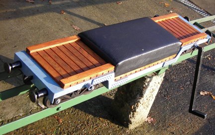
Driving Trolley build Truck 1 Truck 2 Truck 3 Truck 4 Truck 5 Truck 6 Truck 7 Truck 8 Truck 9 Truck 10 Truck 11 Truck 12 Truck 13 Truck 14/15 Truck 16 Truck 17 Truck 18 Truck 19 Truck 20 Truck 20/21 Truck 22 Truck 23 Truck 24/25 Truck 26 / 27 / 28 / 29 Truck 30 / 31 Truck 32 Light flasher |
|
Construction Days 26 / 27 / 28 / 29
|
|
Early morning start
|
|
|
|
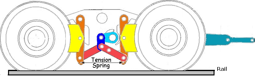
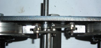
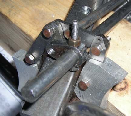
| Above is an assembly
from the drawings of the individual parts of the braking system so that a
"feel" can be obtained for how the system works (added on Thursday 26th May
2010).
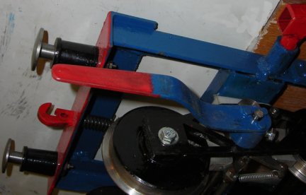
The parts coloured Yellow are the Aluminium Brake Blocks, the other parts are all free moving when the operating arm, seen at the right hand side is lifted upwards. How the breaking system works.The blue lever is pulled upwards by the driver. This rotates the light blue part anti clockwise. This in turn pushes down on the dark blue part which in turn act on the red parts which impart the force acting on the orange levers applies the yellow brake blocks onto the wheel treads. The dark blue part is necessary as it acts as a compensator for if say the left hand wheel is brakes then the pressure if moved to the right hand wheel in such a way that equal force is applied to both wheels. Without this part the brakes would not be as effective if there was any error in the construction or when ware occurs of the aluminium blocks this will also be taken up by the dark blue part as described earlier. |
|
|
So this is as far as we reached
yesterday. Now comes the very complicated part as the drawings do not show
the general arrangements.
In fact this has made me study the drawings very carefully and only do something when I am absolutely sure that it is right. It was at that moment I decided to do the drawing that is shown above but did not included it in the web site at the time. |
|
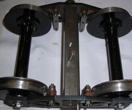
Here we have the four brake hangers in place. |
|
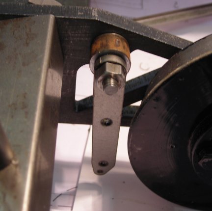
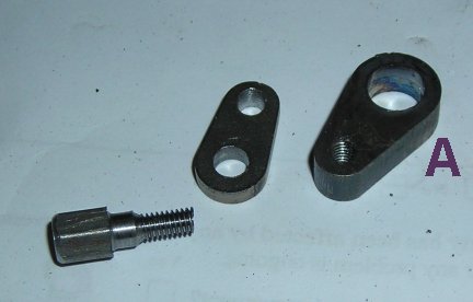
From the brake lever arm is the large piece and this links to the smaller piece by the specially made bolt. |
|
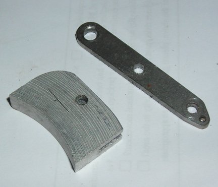
One view of the brake shoe and the brake lever |
|
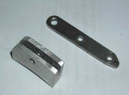
Another view of the brake shoe clearly showing the slot milled in the back and the rounded top as it was found that the brake shoe did not fit without the rounding. |
| The whole assembly loosely put together so that checks can be made that it is all correct - and a measurement taken for the position on the actuator arm of the larger piece three picture above marked "A" | |
|
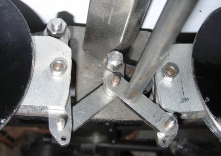
If the front view was amazing showing the complexity of the braking system then this picture shows how it is very complex! |
|
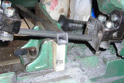
Cutting the steel for the foot rests
gave cause for thought and in the end Paul and i came up with the idea use
a template and obtain the angle.
This was al very well but there is little to no space behind the saw but in the end all four legs were and and the four foot rests. |
|
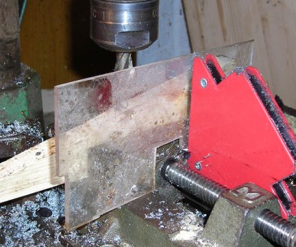
Next came the decision time as to
how to drill a 1/2" hole in the leg at and angle.
First was tried a drill centre followed by a 3/8" drill. The centre was ok but the drill bent but did get through. Then the 1/2" was tried and that was a no no as it started to show signs of not cutting and .... well it was decided that why not use a 1/2" end mill and cut through. the picture shows the set up and just in case the 1/2" End mill broke then the plastic would have take some of the energy out of it !!!! |
|
You can see that it was a successful
task overcome and all in all it took 1 hour 15 minutes to cut to the steel
and mill the holes.
All being well and fine weather the legs should be welded to their spigots which have all ready been machined up to fit the holes and then the foot rest welded on. An attempt to obtain end caps for the steel will be tried or if not available wooden end caps may be made. |
|
|
|
Construction Day 27
|
|
|
The big decision was how to link
for certain the brake lever and its shaft.
A roll pin was tried but the hole drilled to large so it was tapped 4BA and a bolt put through. This will be lock nutted and the surplus bolt cut off. The final item to be made is the brake operating lever. |
|
The buffer beams have been re-painted. |
|
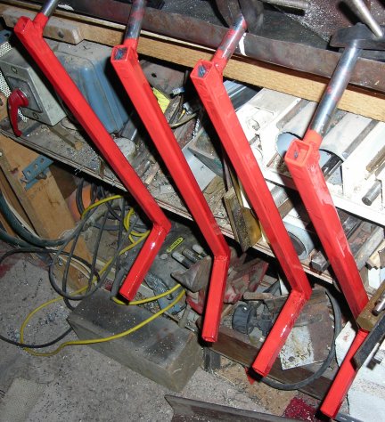
The legs have been made and painted. |
|
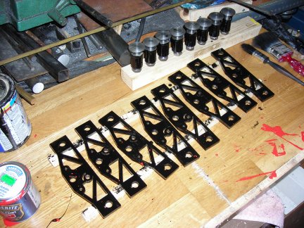
Lastly here are the painted frames .. .one side only |
|
|
|
Construction Day 28 |
|
|
|
|
After all the painting yesterday and a soggy cold start to the day today the casting project for the second set of brake blocks was put off. |
|
|
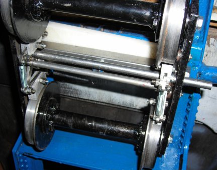
Instead the first truck was built up to almost completion without the brake handle which will attach to the section of steel rod protruding from the right hand side of the bogie. |
|
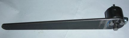
Here is the nearly completed brake
handle requiring final adjustment to miss the side to the truck when operated
under all conditions.
This will necessitate bending the handle near to the boss and then bending again so the it forms a "Z" shape. This will be done hot with the steel brought to red heat. |
|
|
|
Construction Day 29 |
|
|
|
|
 |
It was late afternoon that work started
in the workshop after a very enjoyable lunch with the Maidstone Model Engineering
Club.
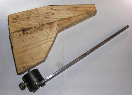
A wooden pattern was made up to bend the handle so that it would a: miss the frame when straight b: miss the frame when a tight right hand turn was made. |
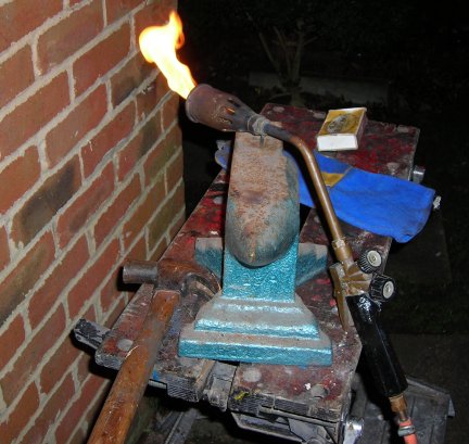 |
Here is the simple foundry anvil
which originally belonged to my father and passed to me on his death in
1973.
The torch is that which I have used for boiler making!!! Note the safety heat glove !!! |
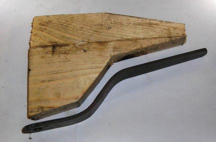 |
After a few minutes the handle was
bent to pattern shape and painted ready to be fixed in position.
As soon as the foam for the seat arrives the seat can be made and the job completed.
|
 |
The brake handle has now been fitted
to the truck.
All that now remains is to make the seat when the foam arrives and then take the truck to the track for a test run. |
If you have any comments / questions about the project then please email me ...
|
|