Building a Polly VI
locomotive from a kit
Kit 7 |
|||||
| Kit 1 | Kit 2 | Kit 3 | Kit 4 | Kit 5 | Kit 6 |
| Kit 7 | Kit 8 | Kit 9 | Kit 10 | Kit 11 | Kit 12 |
A word of warning to builders
If you are going to run your loco on air you will need to thoroughly oil up all the moving parts. This however will result in loads of oil being splashed about and that which goes onto unpainted parts that you might be thinking about painting later will result in lots and lots of cleaning up and degreasing.
So before running on air MAKE SURE ALL PARTS THAT ARE ON THE CHASSIS THAT YOU WISH TO PAINT ARE PAINTED and save yourself hours of work which I had to put in removing unset paint due to oil residue on the surfaces I wrongly thought were clean.
Kit 7 has the following parts
Draincocks Operating Rod
Reach Rod
Cylinder Cladding
Blast Pipe Tee
Left Hand Steam Pipe
Right Hand Steam Pipe
Steam Tee
Steam Conn. Nuts
Blast Nozzle
Blast Pipe Nuts
Blast Pipe Connectors
Draincock Bolt
Draincock Lever
Latch
Reverser Stand
Pole Lever
Latch Plates
Latch Clip
Lever
Spring
Bottom Bolt
Various Spacers
Rear Bolt
One advantage of having bought kits ahead of when they are required is that when various parts a Kit require painting it is possible to prepare and paint ahead of when they are required to be in stalled, thereby, in this case there should not be a hold up in the goal of running the loco on air on the completion of Kit 7.
A club member has loaned me the necessary connector to go between my compressor and the Steam chest in let and I have checked it and it does fit my air compressor line. I have been told that the screw fitting is 5/8" x 26 tpi BSB (British Standard Brass)
5th January 2015
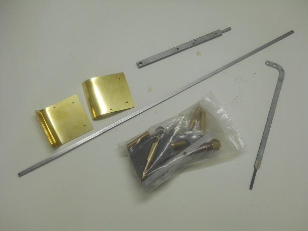
The parts from Kit 7 which need painting were gathered together and cleaned up with white spirit and then given a coat of metal primer.
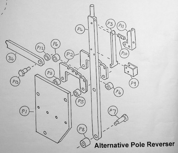
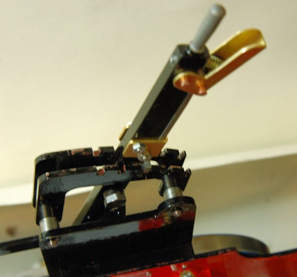
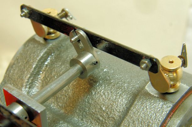
Time to start Kit 7. My Kit 7 has the pole reverser. Opposite is the plan but particularly part 34 is not a straight bar but more like a hockey stick with two holes in the end of the curved part and a threaded rod in the other.. The part P1 was also a different shape where the sloping edge the actual part was curved to go round the rear wheel.
Sorting out the filing of part P3 was also difficult but I achieved it in the end but also needed to open out drill holes for the two copper rivets.
The total time to sort it all out was about 5 hours but a lot of fun.
There was a lot of work to do here to make a good fit so do not rush it - it is not a 5 minute job.
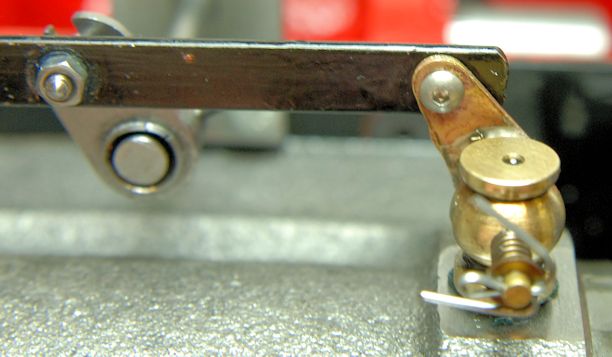
No mention, I could find, is made of the recess at the rear of the pole for the spring P10.
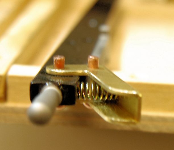
Note that the narrower spacers are between the ratchet plates and the wider ones used as the stand off from the Reverser Plate.
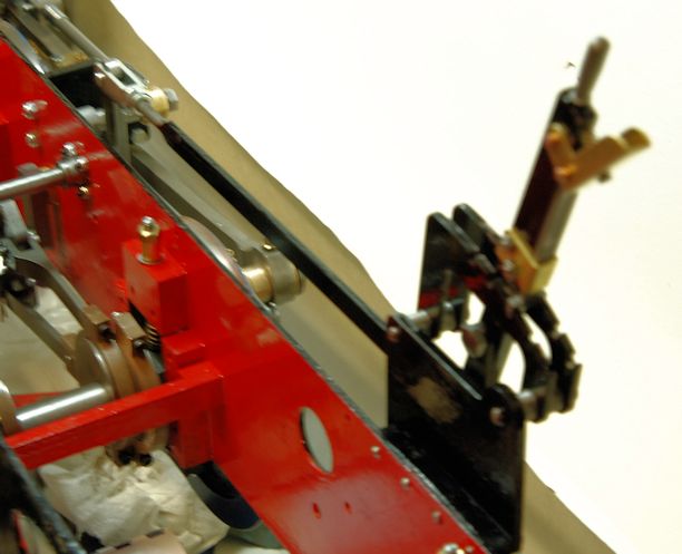
So I have now reached the place in the build instruction which has the heading SETTING THE VALVES.
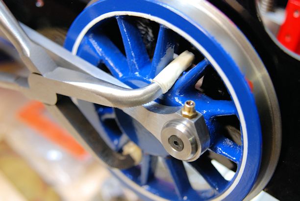
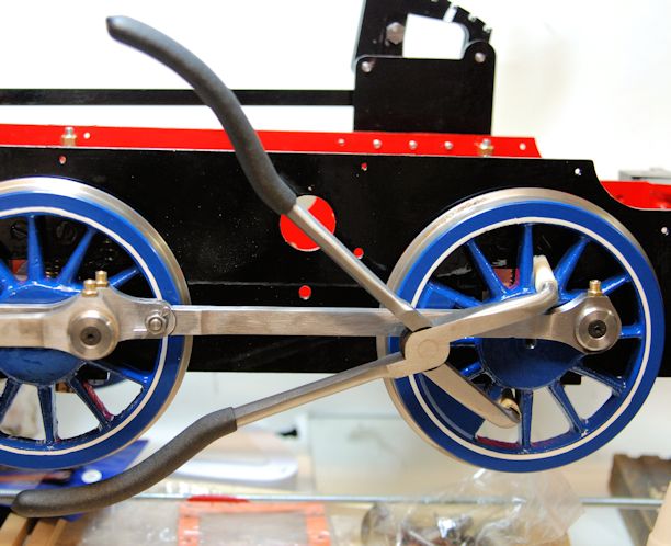
Then early in the paragraph is mention of rotating the wheels. Well with all the parts now fitted turning the wheels be simply grabbing hold of the two rear wheels and turning by hand is just not possible for me so an early task for me in the workshop will be to make up an arm which can be used to turn the wheels by bearing on the wheel spokes.
It was amazing how easy it was to turn the wheels with less then 1 foot of leverage.
The did the job very well of turning the wheels to set up the valves which was relatively straight forward when I understood the build instructions.
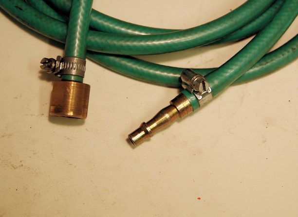
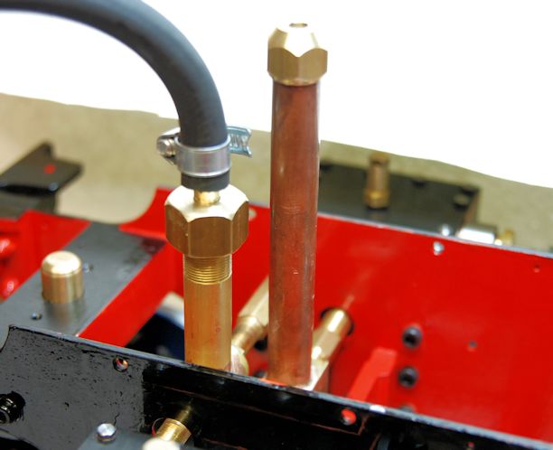
Whilst I had been loaned a suitable connection to the steam inlet by a friend at the Maidstone club I used that as a patten to make my own up as I also wanted to have a regulator in line so that air could be shut off.
The photo show my fitting based on the information told to me and ready to apply pressure from my air compressor located in my garage some 20 of more meters away.
So a through oil round including oil in the steam chests and then slowly up with the pressure and then suddenly the loco wheels turned round. A quick shut down of pressure to check all was well.
Then up with the pressure again and round went the wheels.
After about 15 minutes off with the pressure and other oil round and check for any loose parts, there were none and on with the running in.
In total the loco ran for about 3 hours and is now much freer than before the running in was started.
I was also able to do some fine tuning of the valve settings and the loco now will turn over on a relatively lower air pressure.
LINK TO YOUTUBE VIDEO https://www.youtube.com/watch?v=qpIQF4QHgTc of time lapse of the build so far and First run in air
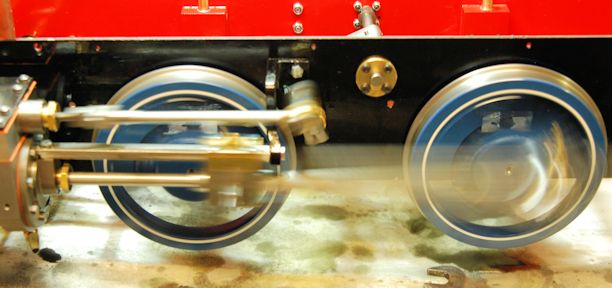
The photo was taken at a slow shutter speed and the wheels were NOT RACING ROUND FLAT OUT !
The fascination of seeing the wheels go round and round has not ceased all day. However the annoying whistle coming from the blast pipe just had to be stopped.
Knowing that sharp edges with air passing causes a whistle (remember a strand of grass held tightly together in your hand and then blown though gave a whistle) so I looked for the sharp edge. There is was on the inside of the blast pipe nozzle. A quick run round with some wet and dry took off the sharp corner from manufacture and the whistle stopped.
I decided to check the valve settings by removing the steam chest covers and made slight adjustments and the chassis will now run on 15psi and chug away quite merrily Forwards and in Reverse needs just a little more pressure !
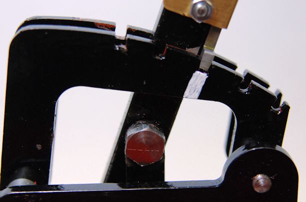
Finding the centre neutral notch has been made easier by painting on a white line.
I left these until last as it requires that the loco chassis is turned upside down which requires careful moving as it is now rather heavy !
The photo shows the actuating arm end and the two Left Hand drain Cocks.
The botls as the smallest Allen screws I have ever seen and I was lucky to have in my workshop the tiny Allan Key required to turn them.
They screw into threaded actuating bar, painted black and then are lock nutted and I also used Thread Lock.
This photo may look strange but remember the loco is upside down !
14th Jan 2015
I decided to move the bolt linking the operating rod to the operating handle round the other way on the drain cocks so that the operating rod was nearer the outside.
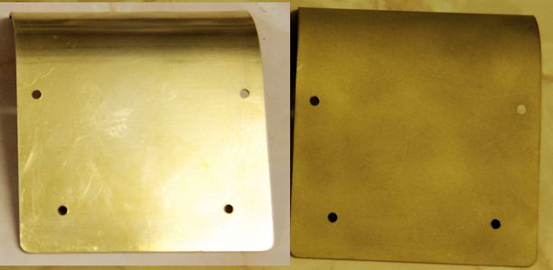
The cylinder cover must now be painted and then lined out. I find that by sand blasting the brass is makes for an excellent key for the etch primer.
The cover on the left is as supplied that on the right is sandblasted in the small cabinet sandblaster I have in my workshop.
After sand blasting the fine remaining grit needed to be washed off and the the covers allowed to dry naturally.