Building a Polly VI
locomotive from a kit
Kit 1 |
|||||
| Kit 1 | Kit 2 | Kit 3 | Kit 4 | Kit 5 | Kit 6 |
| Kit 7 | Kit 8 | Kit 9 | Kit 10 | Kit 11 | Kit 12 |
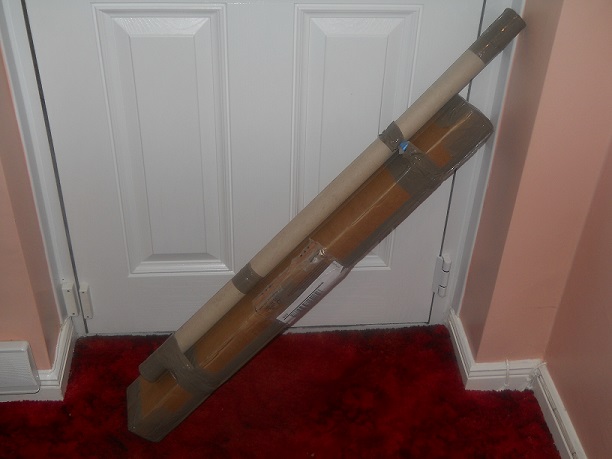
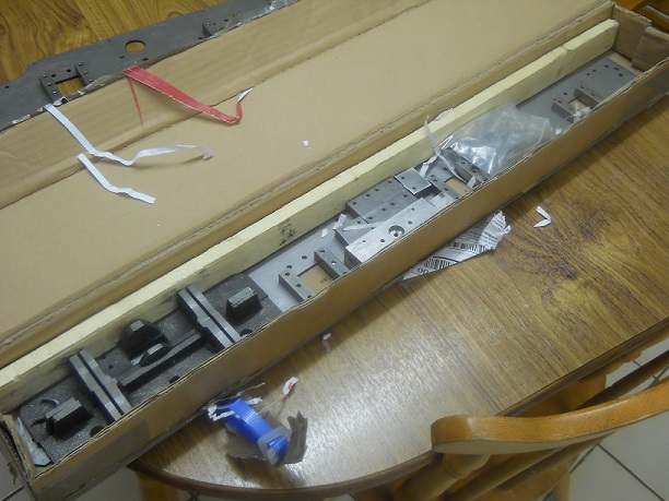
It arrived in two packages which were securely held together and certainly indicated that care had been taken with the packing.
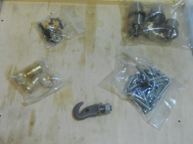
The following was the contents of the packages.
In the long tube were two large plans and a smaller one, the build instructions for Kit 1 which included a list of tools required to complete the assembly of the kit.
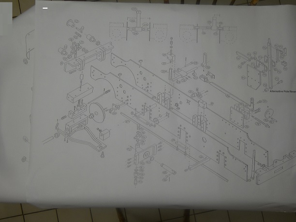
The plans are very detailed projections
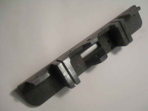
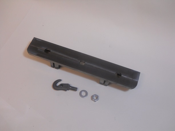
I was impressed with the very substantial buffer beams.
The Axle Horns are already fitted and a locking adhesive apparent.
It is advised that prior to commencement of the erection of the frames that one goes over all the surfaces with emery of similar to provide a good surface for the adhesion of paint.
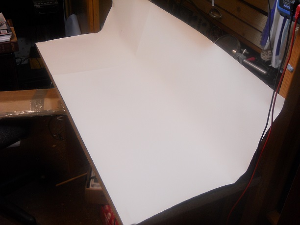
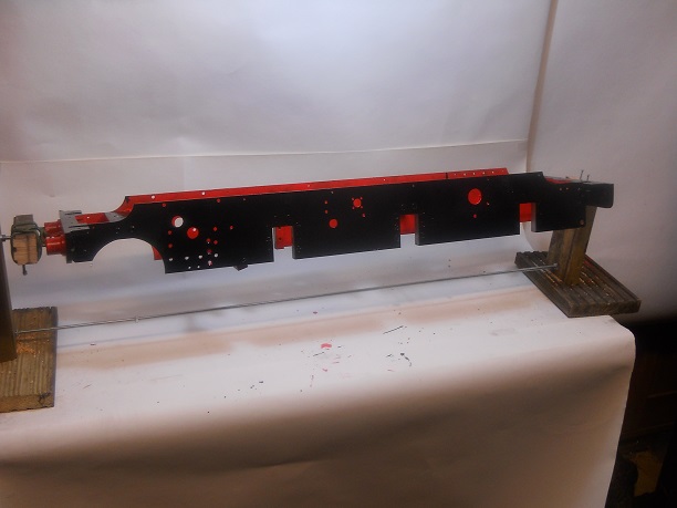
Being ready to start the construction I decided to clear a working space in my Radio Shack, an other of my hobbies is Amateur Radio, and to put down a piece of white paper cut off a roll of lining wall paper to enhance as far as possible any future photos.
The instructions tell that the left and right hand sides of the loco are a viewed from the rear buffer beam looking forward and this I will use as necessary in this commentary.
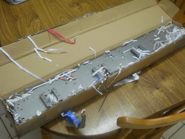
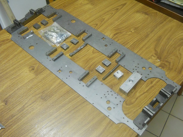
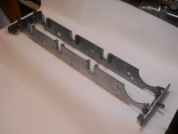
The photo show the frames after I have been over them with emery cloth.
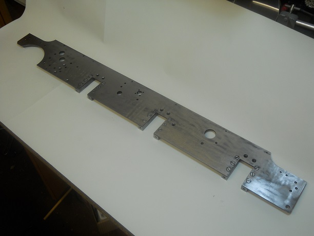
Each frame took about 30minutes to clean up and they have not yet been degreased - that comes later.
This was easily achieved by using a relatively small square file which I had in the workshop. about 0.5mm had to be taken off the overall width and height, making sure the hole remained square.
The instructions are silent as to whether to fit the hook now or later but as I cannot see any instruction to do it later and the instruction sheet picture shows the hook attached I will soon attach the hook and tighten it up.
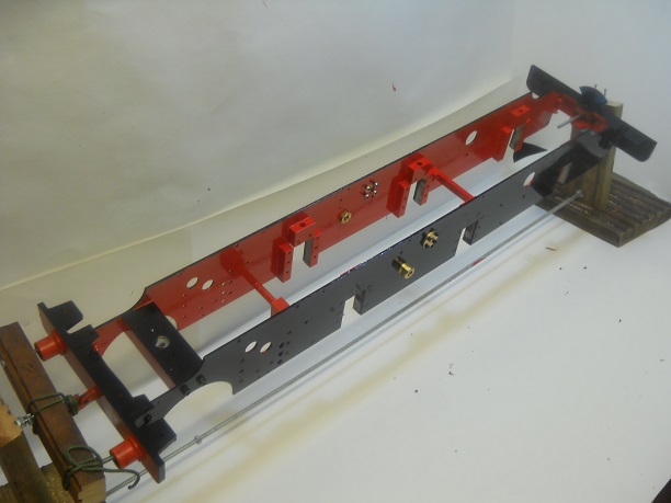
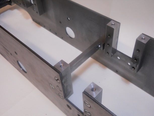
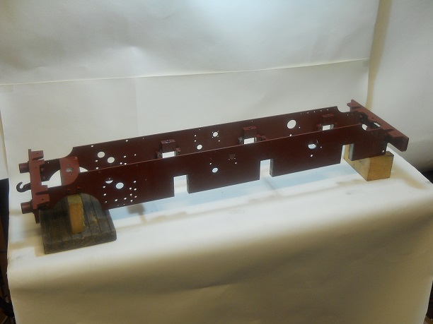
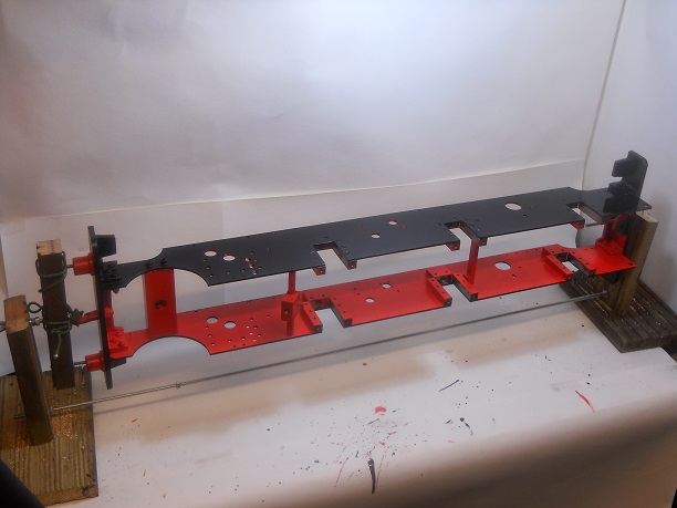
The photo show the frames erected but bolts not tightened yet!
One out of every three bolts holes had to be fractionally eased out to take the final bolt of each set of three.
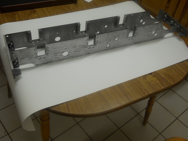
The photo show the frames on the kitchen table with suitable protection and the bolts were tightened. The frames were then turned round end for end to proved the was no wobble in the frames.
In anticipation of a later procedure I am sourcing some "Cellulose Thinners" to enable degreasing of the frames as recommended in the build notes (page6).
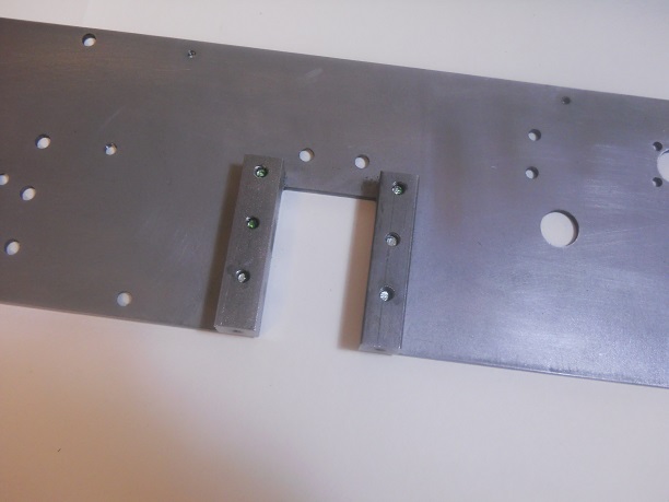
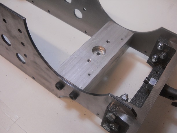
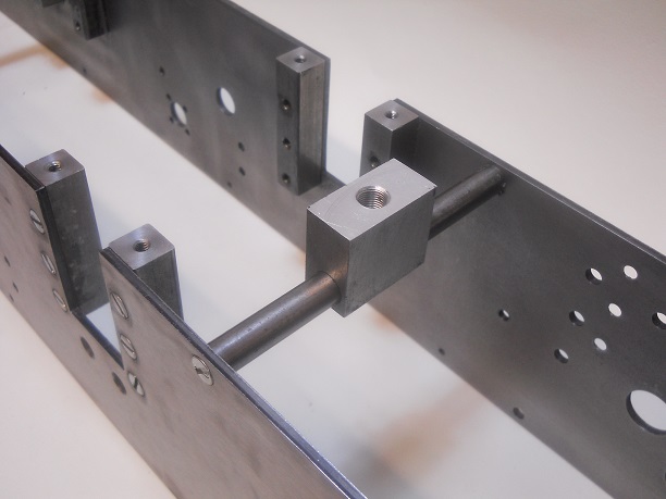
The instructions say "With the frames upside down on the table, fit the Pony Main Stay". However the photo in the instructions shows the frames the right way up so be careful.
I checked the fit of the bolts and the four holes were too small by a little bit so they were all drilled out for a neat clearance.
However I put the stay in upside down as the photo shows and then changed it to the correct way up with the little tapped holes to the front.
This will be done with white spirit and then finished off "outside in the garden" with the cellulose thinners that I was able to source from a local hardware store.
I have decided to removed the pony stretcher and pony pivot as they are aluminum they need a special primer which I have as a spray. When they are dry they will be put back in place.
The photo, not the best I know, shows them hung up to dry !!!
I decided that as my wife hates the smell of fresh paint that the painting should be carried out in my workshop aka my garage.
I have no paint booth and the workshop is unheated so when I paint I have an electric heater on but do not leave it on so the conditions are not ideal. I will try to improve the conditions in due course.
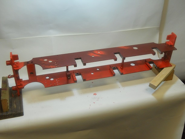
The photo shows the red oxide primer painted.
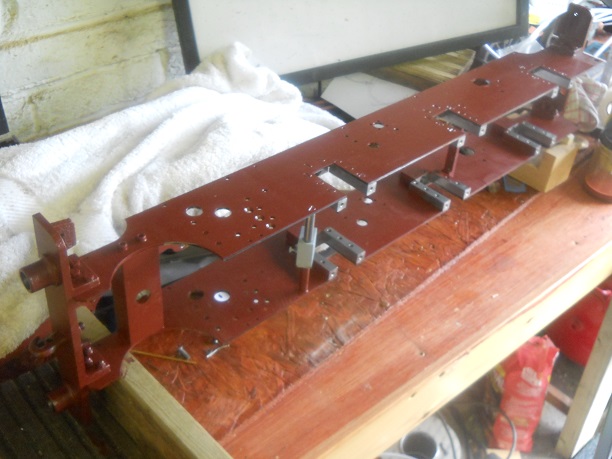
I have also to work out a way to hold the chassis to allow all surfaces to dry. Now that is a thing to think about!!
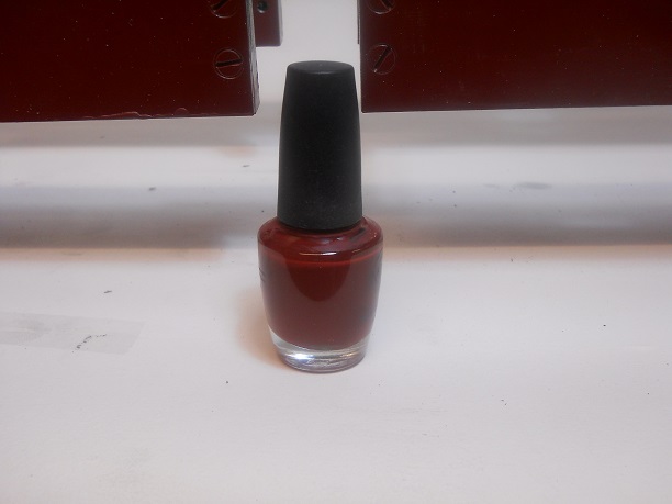
A close inspection of the primer revealed a few small missed patches so I decided to empty out a nail varnish bottle from the set that I keep to identify parts by colour coding. once empty the primer was put into the bottle which having a brush attached was ideal to touch up the missed areas, without having to wash out the brush which remains in the bottle.
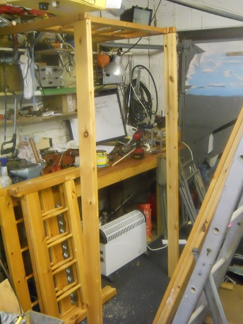
Having considered a paint booth I came up with the following requirements
1. It must be tall enough to stand up in
2. I must be wide enough to take the full length of the loco
3.I must be easy to enter and leave
4. It must not cost too much to make.
Having just removed a set of bunk bed as being surplus to requirement in the house consider was given to whether they could provide the basis.
1. being 6ft 6ins long it is tall enough to stand up in
2. being 3 ft wide is is long enough to take the locomotive which is 35 inches so I can splay out the lower section to give sufficient room to paint round it all
3. I will have the widest part as the entrance so easy to enter and leave
4.There is only some plastic sheeting to buy as all other components are to hand.
So all criteria met ! So let us hope it works !
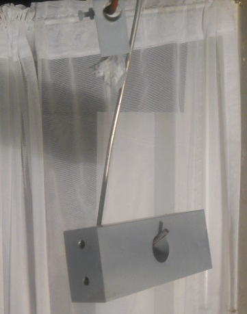
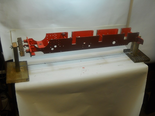
Before I go any further I will be making some simple support to enable the next coat to be painted much more easily.
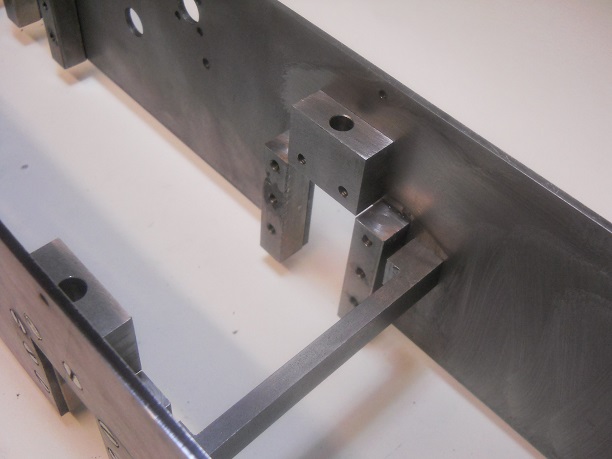
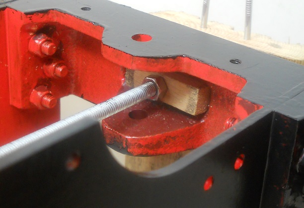
To release the frames will need this threaded rod to be slackened.
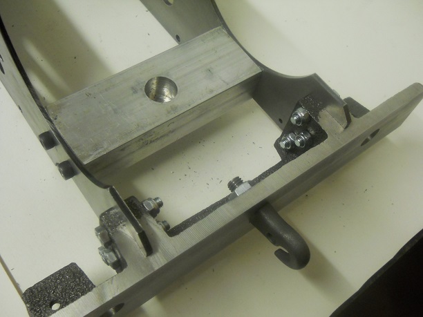
After much thinking the rear buffer oblong slot was measured and a simple piece of wood fashioned and hole drilled in its centre and then pushed into the slot as shown in the photo.
This maintains the support in the centre without it slopping side to side which will make the next coat of paint go on much easier.
A simple solution !
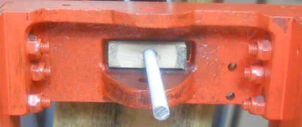
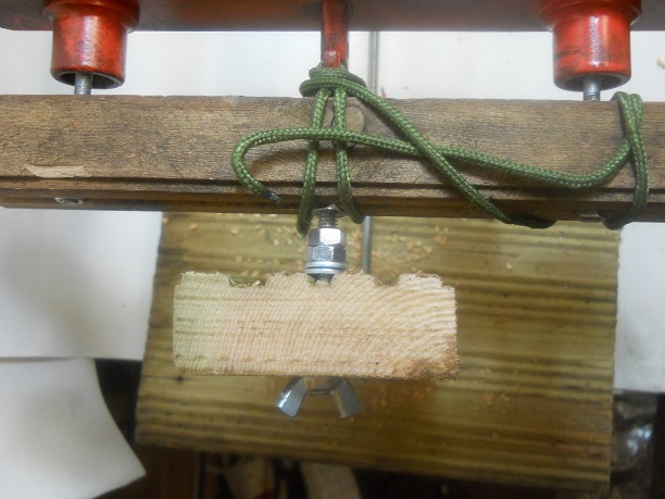
Modifications made to the stand include
1. a piece of cord to keep the hook close to the wood that supports the buffer stocks
2. a washer on the out side to the photo above and a nut on the inside to stop the buffer beam pulling away from the timber
All this proved very successful as the painting of the undercoat of the black was much easier.
Any further improvement I will add in the text as found necessary.
The other improvements made over night are the addition of an additional locking nut, and the cord already mentioned earlier.
Also an additional nut at the other end .
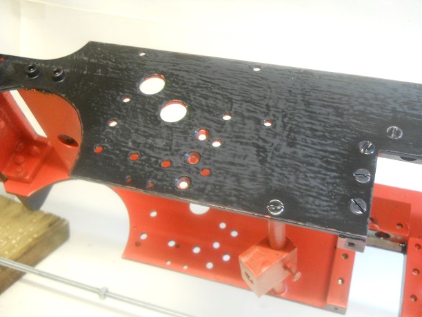
I have decided that the buffer beams will be top coated when it is on its wheels.as it is so difficult to get to the buffers on the, well shall we call it, STAGING.
The second Red Undercoat went on this afternoon leaving the second Black Undercoat to go on tomorrow.
The final black undercoat went on at about Mid Day today so that now just leaves the top coats to do over the next two days as the paint needs 24 hours between coats.
The modifications to the staging has worked very well with little I would change to improve further but that would need more M6 nuts which I do not have !
When all the painting is done there are just a few parts to add which completes the kit and then the frames can harden off until Kit 2 arrives.
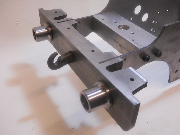
The fianl topcoat is now dry after several days after painting and it is time to assemble the laste 4 parts The two Weightshaft Bearings and the two Rocker Shaft Bearings.
The photo show the complete kit 1.