Building a Polly VI
locomotive from a kit
Kit 11 |
|||||
| Kit 1 | Kit 2 | Kit 3 | Kit 4 | Kit 5 | Kit 6 |
| Kit 7 | Kit 8 | Kit 9 | Kit 10 | Kit 11 | Kit 12 |
I have today heard from Polly Model Engineering that the final two kit are ready for dispatch and they should be with me on Friday 30th January 2015
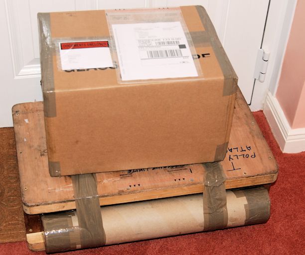
Late afternoon the two heavy parcels for kits 11 and 12 arrived. They were both packed very well as usual.
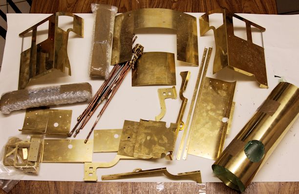
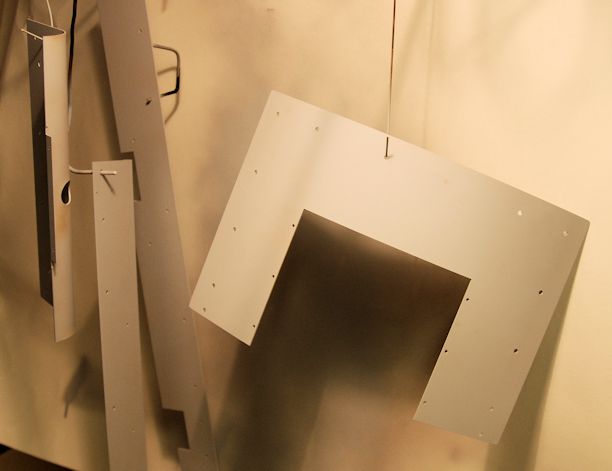
I have today applied the etch primer to some of the cab and running board parts.
There are many more parts in brass that need the same primer and I have to allow 24 hours before applying an under coat.
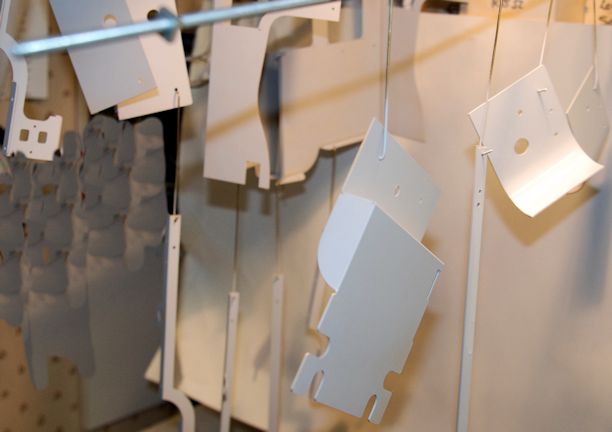
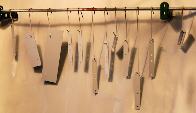
Here are many more parts which have had the special etch primer sprayed onto them.
As with the others I must wait 24 hours to allow it to properly cure.
I have now used 1 1/2 cans of the etch primer!
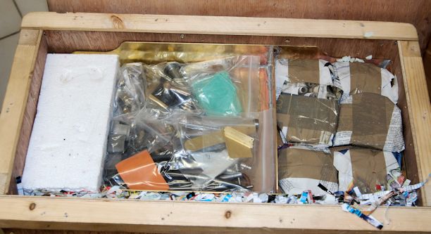
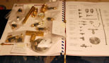
I have now sorted out the many pieces of pipework associated with this kit 11
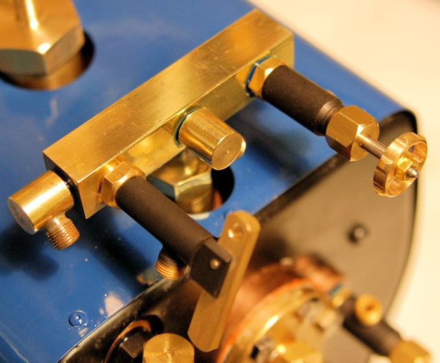
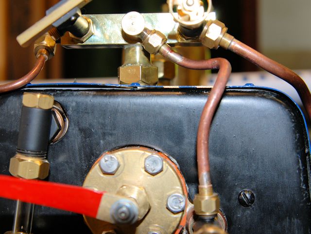
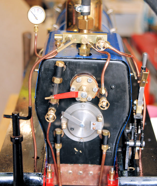
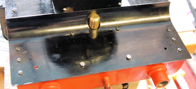
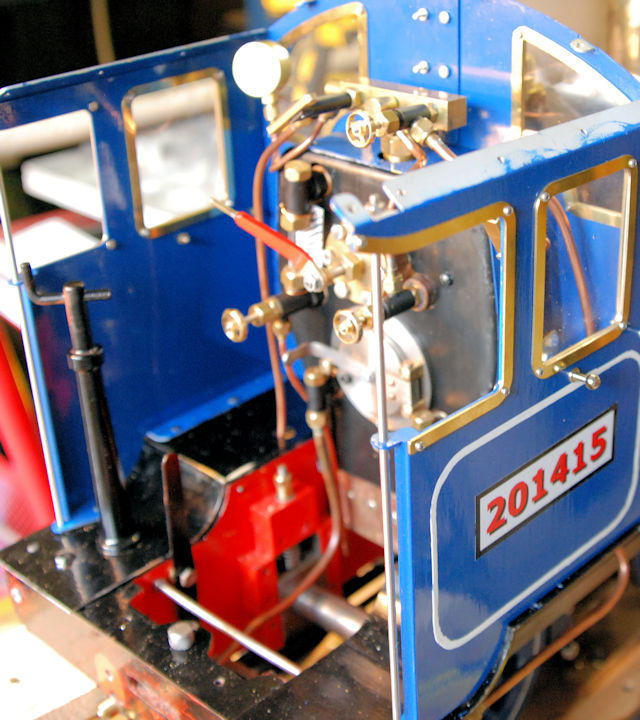
So now we come to more plumbing but it is finial finishing off and we start with the rear of the Smokebox, the Backhead Fittings
The build manual recommends the use of Lock 'n' Seal and this I obtained by mail order previously I have used plumbing tape.
May suggest that you do a trial run of all the pipework, with the exception of the Water Gauge before you used the Lock n Seal then it will be much easier to set the fitting to the correct angles especially on the turret. I had to redo two fittings as they were no quite at the right angle.
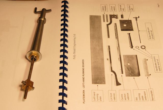
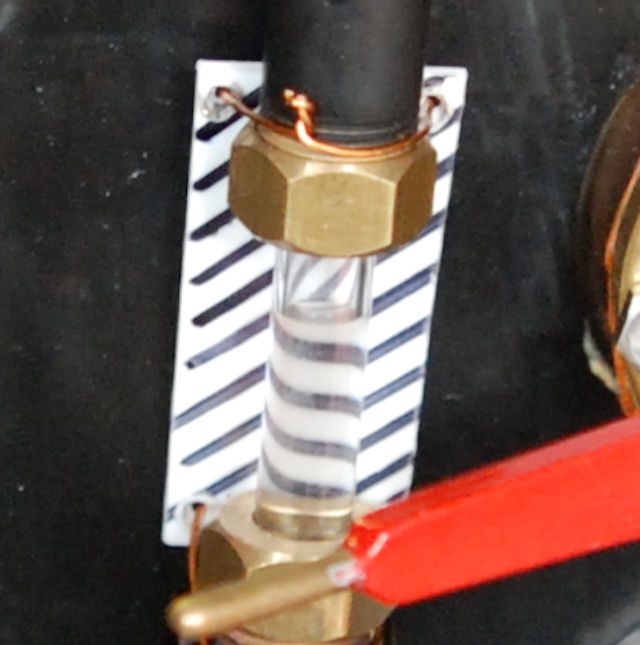
To make sure that the water gauge is lined up, as recommended in the build manual, I turned in my workshop a suitable bar that nicely fitted through the top fitting and into the bottom fitting. After fitting with the use of the Lock 'n' Seal it was left to set before fitting the glass tube.
The sight glass s 7mm diameter which has to be cut to a length of 42mm and then the ends heated in a flame so that the sharp edges are rounded.
Next the three clack valves were fitted followed by the fire hole door. The fitting was tightened well down and the fit is very good in deed.
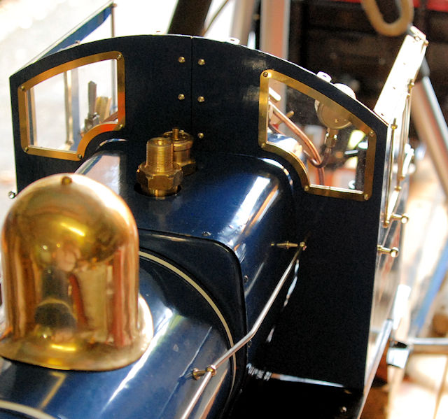
As the Turret is a prominent I decided to polish it prior to fitting.
All the fittings were then left to allow the Lock 'n' Seal to set fully before adding more to the Turret.
The Fusible Plug was, on the recommendation of the boiler tester, fitted prior to the Hydraulic Test at my club so that is completed.
The whistle operating is test fitted as at the moment I cannot work out the pipe run so final fitting will made later.
The injector and the steam valves have been fitted as described in the build manual.
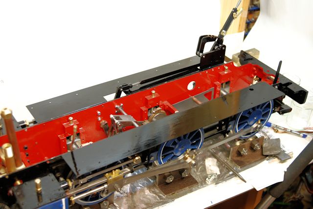
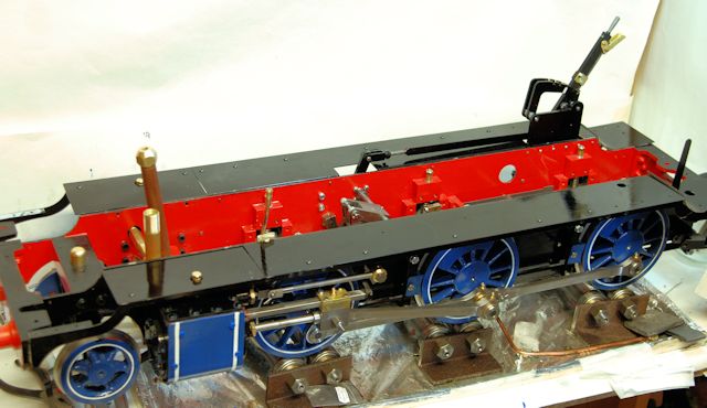
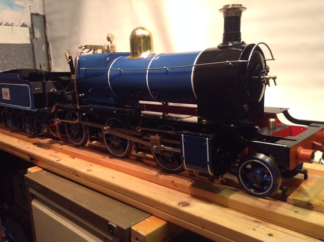
With all these fittings in place now comes the fitting of the plate work so the boiler and smokebox will now be fitted to the chassis.
Today work started on the Platework.
Firstly though I replaced the axle pump strap onto its eccentric which had been removed for the running in period. Some easing of tightness was necessary but soon completed allowing bedding in tightness to remain.
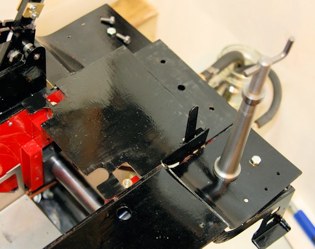
Then the right hand side Running Plate needed to have a little cut away provided to allow a steam pipe to pass through for the Injector. I decided that instead of a square hole that a round hole would look nicer with square edges to the existing cut out. So out to the workshop and that was achieved in a few minute with some tidying up file work and the paintwork will need to be touched up too!
The left hand side was a simpler screw on task. It already has a hole through which the steam pipe to the whistle will exit.
So on with the platework when the fishplates as in an undercoat condition so saving one day. The final coat can be given when the remainder of the touch up is carried out.
So first it was the Valances that had to be assembled. All quite straight forward but one set of holes just had to be opened out a little and these are used down the sides of the other plate work as shown below.
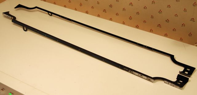
Strangely the centre piece is held down by 4BA bolts and I can see no reason why they c0uld not have been say M4
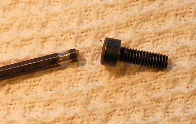
Thinking ahead to the fitting of the smokebox and the fact that I am doing it after fitting all the platework I have had to find a way to do up the bolts. I decided to change to cap bolts M4 and to grind an Allen key so that it can be used as a slight angle.
The photo show the end of the Allen key rounded a little and then a slight indentation a little higher up to allow the Allen key to lie at the slight angle to pass under the valance.
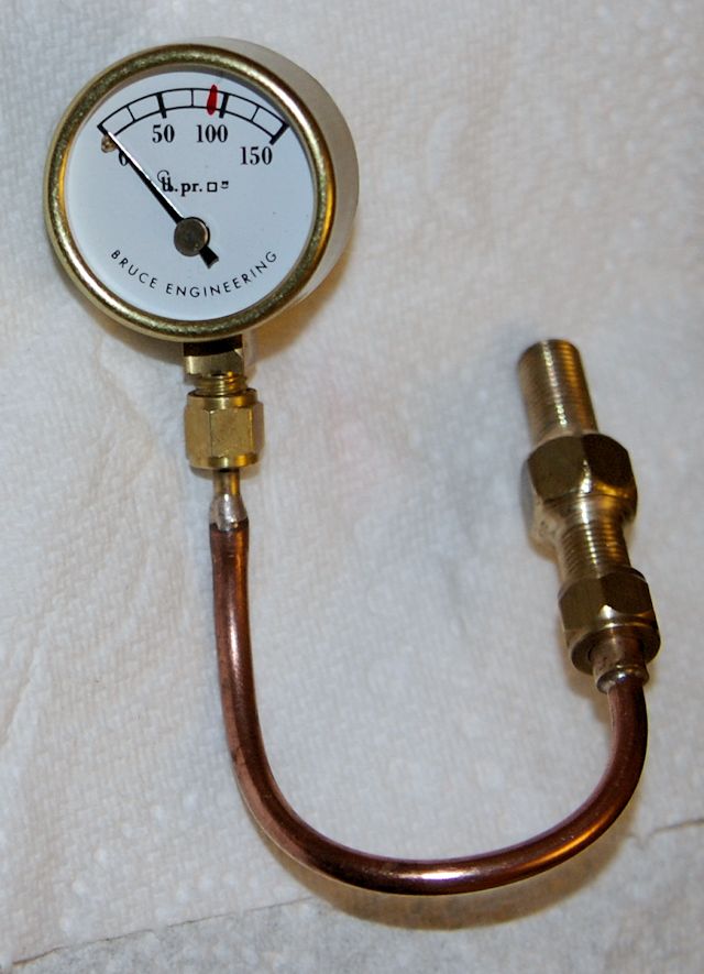
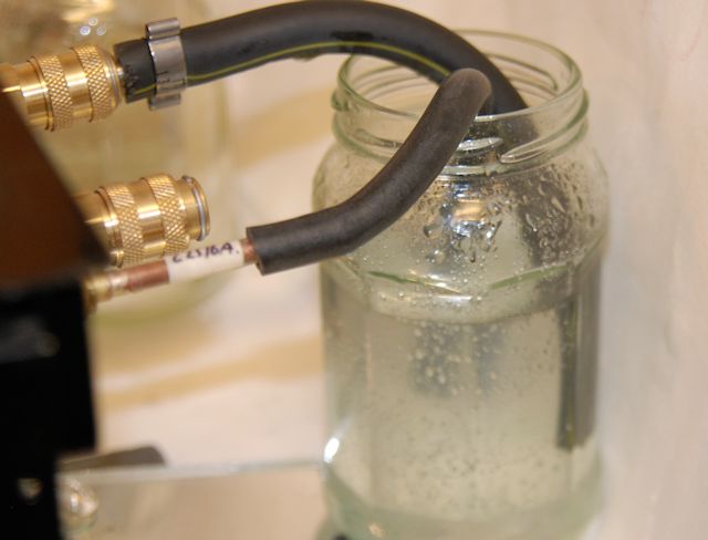
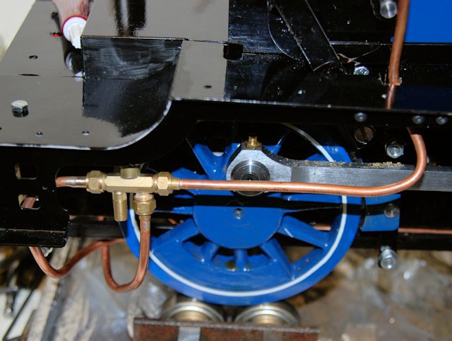
Today was the day to test the axle pump. The inlet was connected to the small hose, the nearer pipe and popped in to a jar of water, with the high pressure connected, at the rear, with the supplied piece of pipe with the high pressure fitting.
It did not take long to empty the small jar of water all over the work bench as the banjo nuts top and bottom of the pump were not tightened down fully onto the pump nor the feed nor overflow connections fully nipped up.
Once this was achieved the pump worked very well.
With that test completed I can move onto installing the boiler and coupling up the pipe work.
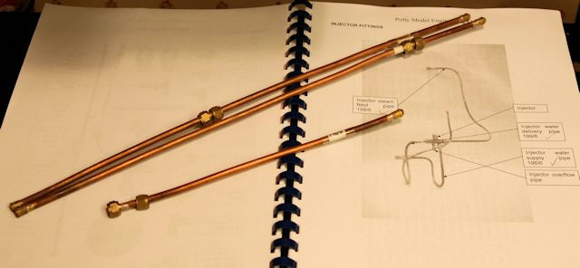
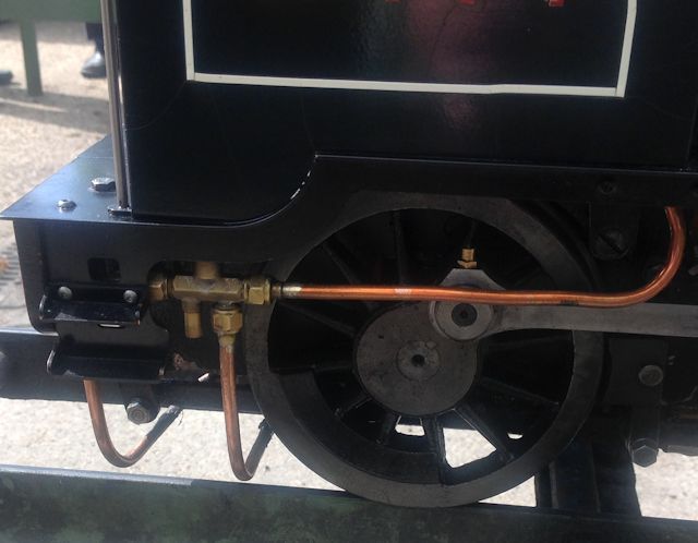
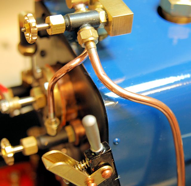
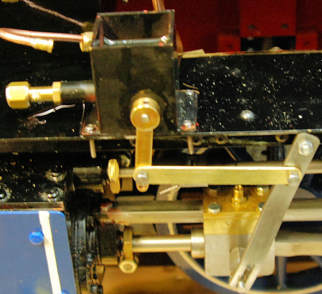
Work commenced on the fitting of the injector after to seeing a similar Polly VI which gave me a very good idea as to the pipe runs ( see photo adjacent ).
I found that there was a silver solder blob on the feed pipe ferrule which prevented the nut going properly over the ferule but that was quickly sorted out with a file.
The route of the pipe run was worked out using pipe cleaners and the bending of the pipe will be done soon.
The most difficult pipe to link up was the water inlet as there was little room so I had to slacken off the nut holding the fitting through the rear plate, then tighten to fitting and re-tighten the nuts holding the back plate fitting.
Pipe part 202 was a bit of a mystery to me until I emailed Polly and was told it was the steam pipe to the blower valve. It has an very awkward bend profile but I was able to achieve it first time.
Today I decided to polish the steam pipes to the Blower and Injector.
Also I completed what I believe is the last bit of painting but will not know that until the final assembly is completed.
The loco chassis with boiler attached has now been moved into my workshop ready for a hydraulic test to check that all is well before the actual test at my club.
I was able to fit the pipe to the steam whistle as now I know the route for the pipe to take including passing through the running board.
I also fitted the exit pipe for the drain down of the sight glass.
Both of these pipe were given a polish before fitting.
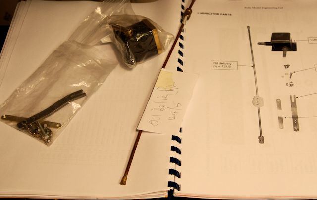
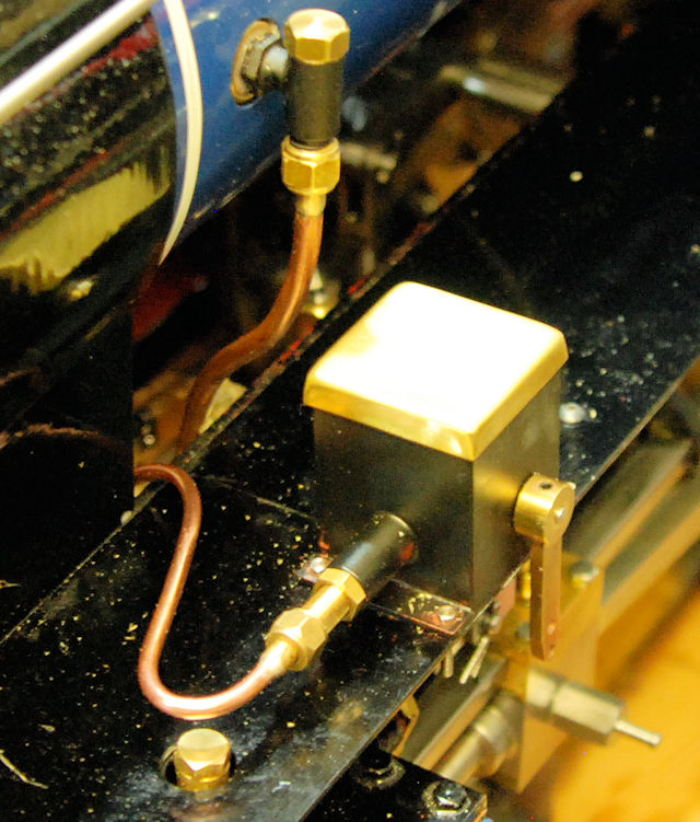
I have now installed the mechanical oiler as far as it is bolted down and the pipe fitted. I had to use pipe cleaners to ensure that I bent the pipe in the right directions.
The first bend must be made a tight to the nipple as it can be else it just will not fit, I nearly had to bend the pipe again as I was 1mm too far away for the start of the bend but with a bit of manipulation I was able to have the nipple join with the union.
The other end of the pipe takes a very tortuous route under the smoke box and onto the end of the mechanical oiler which has a flat faced union.
There now remains the assembly of the linkage.
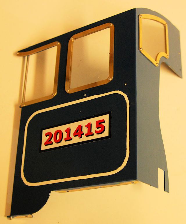
Today the cab windows were installed. I have to remove the layer of paint where the plastic sheeting sat else it would not fit. With the paint removed the fit was perfection.
I was to fit the link between the two cab sides but found I have not put a top coat of paint on the item.
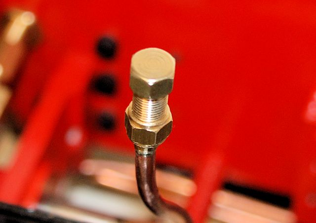
Checking the mechanical oiler I found it was not pumping oil. On the forum for Polly Models there was a good suggestion to make up a part which could be screwed onto the oiler with a very small hole in the end, small enough to stop the spring coming out and thus also to retain the small ball bearing. in the photo you can see the disconnected pipe and the new fitting on the front of the oiler.
I still could not make the oiler pump oil so I decided to take it apart.
Behind the new fitting of the brass threaded oiling mechanism which can be removed including the plunger and its return spring. I immediately saw that even with the plunger at the full uncompressed extent of the spring the little hole in the side was still covered by the plunger. There was no chance for oil to enter and then pushed forward by the plunger. So I fitted two small washers behind the spring which then meant that I had to insert the plunger from the inside of the oiling chamber and make it poke through the black part. I then put the brass part back into place and waggled to the operating arm. It took some winding in and out of the threaded portion but eventually oil came out from new part.The new part was removed and the pipe reconnected and more waggling caused oil to flow drip by drip from the open end of the pipe which had been disconnected from the the steam pipes.
I now need to run the loco on air and see if the motion of the linkage make the oil flow.
I fitted the link plate to one side of the cab but had to drill out the fixings as the tapped holes were in the cab and not in the link. Still no problem and all sorted.
I also fitted the front Running plate but the fit whilst it lines up with the fixing holes does not look a good fit. May be one day I will see if I can amend it to make a better fit.
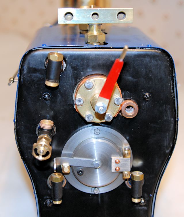
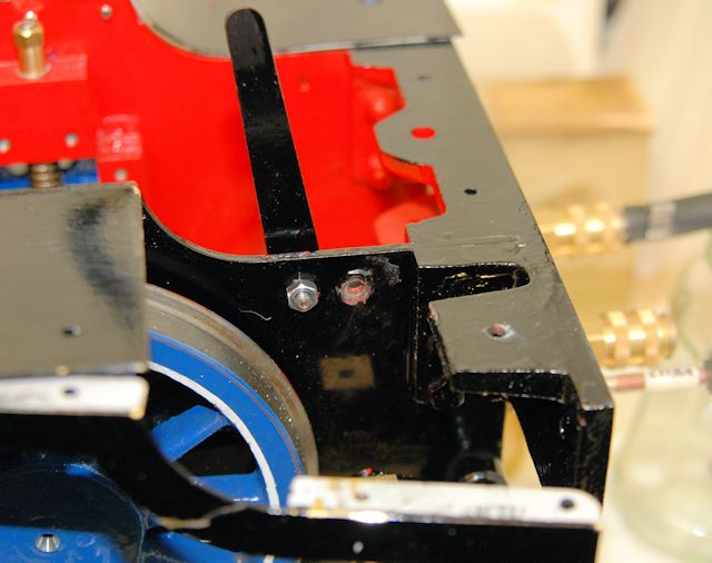
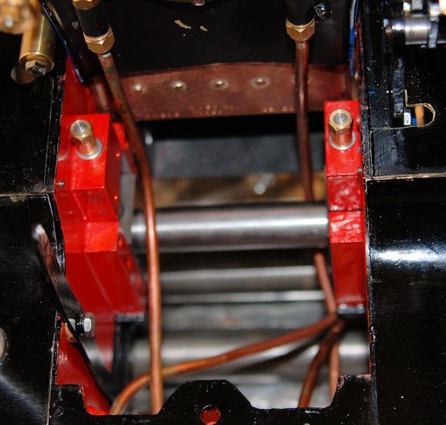
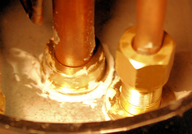
Today was the planned steam test day which started with a satisfactorily hydraulic test to 135psi . Then attention was turned to a steam test. One look in the smoke box by the boiler terster resulted in being told that the holes around the blast pipe and the steam inlet pipe would make the necessary vacuum to enabler the fire to burn highly unlikely. The photo clearly shows the holes / gaps to the pipes.
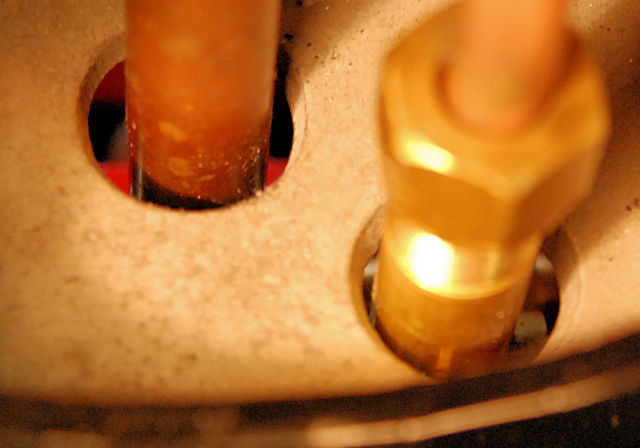
Whilst it looks a little messy it should do the job !
It was also recommended that the bolt protuding into the line of the blast should be removed so that it will not interfere with the exhaust gas flow.
Work was don e to install the two cab sides. One of the most difficult jobs to do as the access to the location positions of the nuts is very restrictive. What I needed but did not have was a socket to hole the nut but not recessed but level with the surface of the socket.
Work was carried out to check the tender pump was working, it was not the entry ball was stuck which resulted in the pump having to be taken off the tender. Both ends were then cleaned up and ball put back in and the pipe reinstalled. Great it now works.
A test of the axle pump with the loco run on air showed many leaks including to the two union s on the bypass valve which needed tightening a little more and significantly from the pressure pipe. A new pipe squeeze fitting was installed on the olive and packing out ot the end of the black rubber hose with plastic tubing and another squeeze fitting solved the leakage problem.
The other pressure pipe was given the same treatment.
Whilst the tender was up side down I made a check on all the unions and found that slight tightening was necessary.
I now hope that the tender pipework is sound
So that I know the position of the on/off valve an indication was painted on the inside front of the tender indicating the closed position..
The great was too tight in the inside of the boiler so some had to be linished off. More may still need to be removed if it is too tight due to expansion, that should be decided tomorrow if the a steam test goes ahead.