Building a Polly VI
locomotive from a kit
Kit 6 |
|||||
| Kit 1 | Kit 2 | Kit 3 | Kit 4 | Kit 5 | Kit 6 |
| Kit 7 | Kit 8 | Kit 9 | Kit 10 | Kit 11 | Kit 12 |
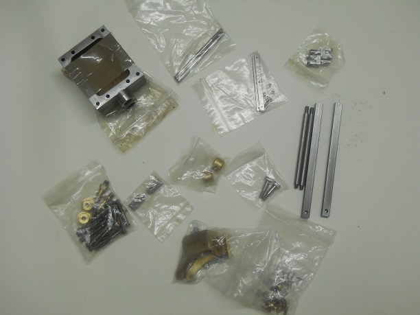
Kit 6 has the following parts
2 Steam Chest Stuffing Nuts
2 Steam Chests
2 Guide Bar Brackets
2 Valve Rod Boss Bolts
2 Valve Rod Forks
2 Intermediate Valve Rods
2 Guide Bars
2 Valve Rod Eyes
2 Valve Rod Bosses
Valve Rod Pins
2 Valve Rods
2 Draincock Links
4 Draincocks
2 Blanking plugs
2 extension Bushs
Valve Rod Nuts
Steam Chest Gaskets
Steam Chest Covers
Before starting Kit 6 I checked to see if the coupling rods slide easily into the Cross Heads. They did not so I used wet and dry paper to bring the thickness to a size that was a good slide fit without and binding between the Crosshead and the Coupling Rods.
The Valve drive nut as supplied is fractionally too wide for the slot in the valve. This is referred to in the build instruction but rather than taking a file to resize I used wet and dry and soon brought to size.
I much prefer to use the wet and dry as I am less likely to take too mush off!
Putting the Crosshead Pins into their location was very tricky as one has to carefully align the hole in the coupling bearing with the hole in the Crosshead. The build instruction says to do it with the wheels in a full forward position of the coupling rod but I found that this prevented me putting the pin into place. I found that just a little after fully forward was right as the connecting rod boss was out of the way.
The Build Instruction say that work has to be done to allow clearance for the wheels!
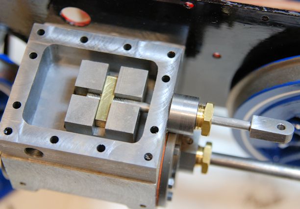
I decided to check if the Guide Bars would go through the Crosshead and found that on both items it met obstruction at the point of the oiler.
On disassembling the Crossheads and removing the caps I found that the oiler protruded a fraction into the path of the Guide Bar. A few moment work with wet and dry removed the obstruction and the Guide Bars passed through easily ready for when they are to be fully installed.
The Crossheads were fully re-assembled.
I decided to crack on and pre-assemble the Intermediate Valve Rod Assembly as it needs the use of Loctite to ensure they are fixed in position and that will need to be left over night to fully cure. This mean that when the painting of the Guide Bar Brackets is complete and ready to install the other parts will also be ready.
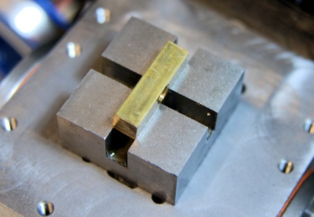
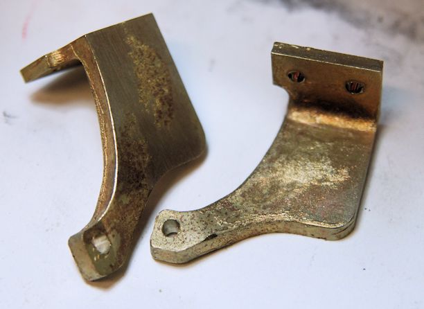
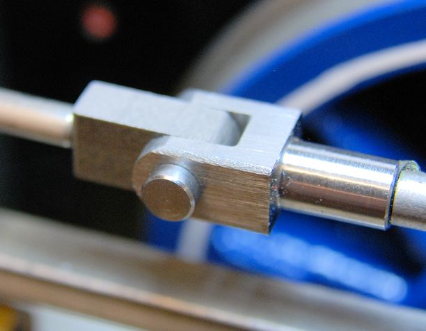
However this was no as straight forward as I expected as the forks did not fit over the Valve Rod Eyes the forks being 0.3mm too narrow. So out to my workshop and a quick use of my files and it was resized.
As you see in the picture the two pieces now fit and the pin fits too.
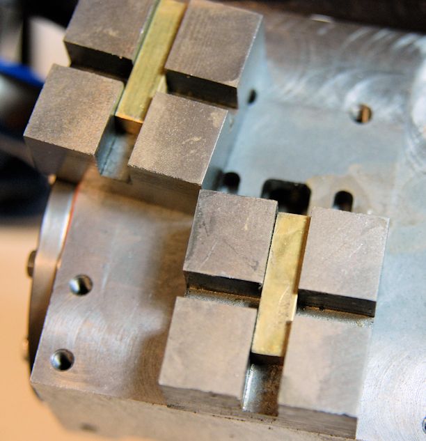
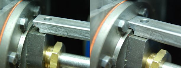
I check that in that position the Guide Bar Bracket would not fit either.
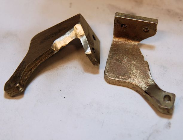
So I cut away the end of the guide bar as shown in the right hand part of the picture.
Now all will fit well together.
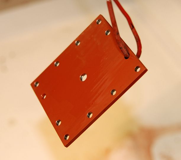
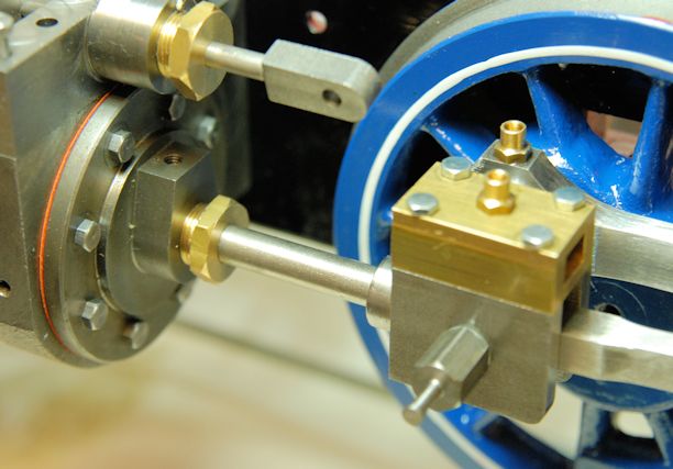
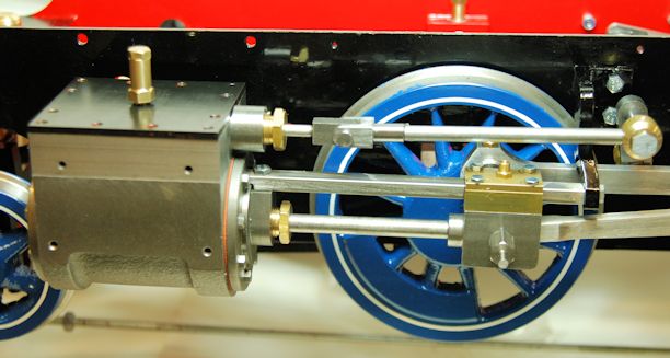
The final parts of Kit 6 are now in place, if only but temporarily as the Steam Chest cover needs its top coat of paint to complete and the brass component on the top needs to be fitted with washers which I do not have but no doubt I can easily obtain them from Polly Engineering.
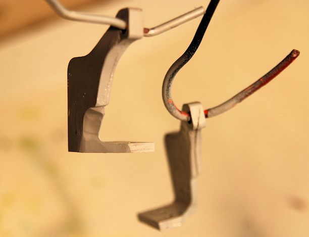
The guide bars and their support brackets. As well as the shaping at the front end of the Guide Bars on my loco the right hand Guide Bar had to be shortened by 0.5 mm to allow a good fit to the bracket. I had noticed that is was that fraction too long when placed against the left hand side Guide Bar but decided not to amend until I was fitting it.
The wheels still go round but becoming more difficult to turn which I am sure will soon ease out when the running on air is commenced.
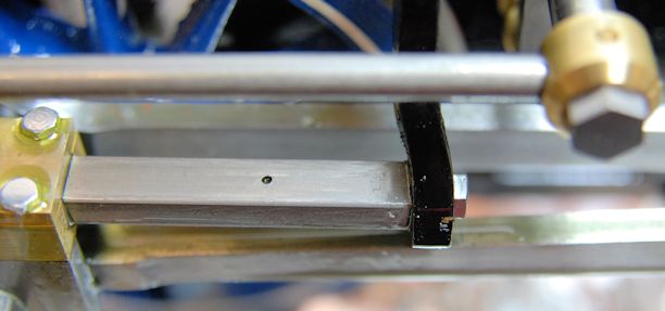
After a period of running in (which happened at the end of Kit 7) I decided that I was not happy with the oiling of the underside of the guide bar which seemed to be none. So I decided to drill a 1.5mm hole in each guide bar about 20mm in front of the end of the support bracket which equates to about the mid point of the cross head.
Now I have no trouble with oil reaching the underside of the Guide Bars.