Building a Polly VI
locomotive from a kit
Kit 4 |
|||||
| Kit 1 | Kit 2 | Kit 3 | Kit 4 | Kit 5 | Kit 6 |
| Kit 7 | Kit 8 | Kit 9 | Kit 10 | Kit 11 | Kit 12 |
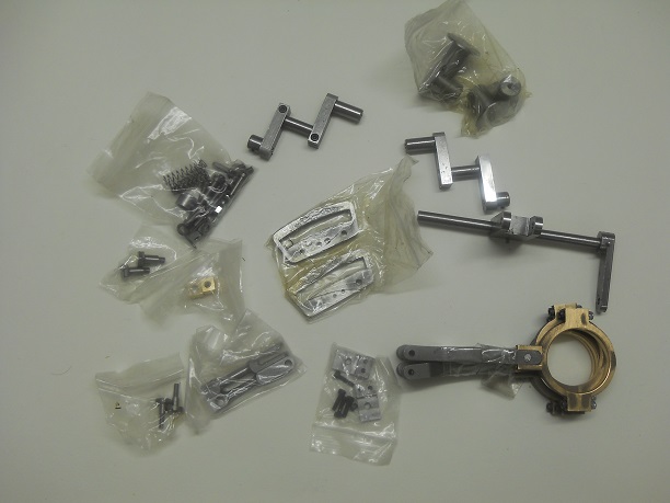
Kit 4 has the following parts
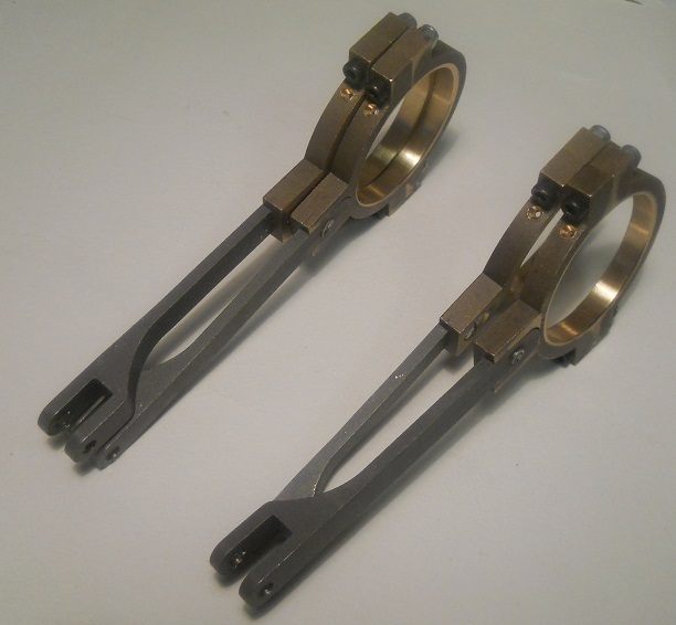
2 Suspension links
4 Buffer Heads
4 Buffer Springs
4 Buffer Studs
2 Trunion Brackets
2 Expansion Links
2 Rockers (complete)
2 Die Block Pins
2 Die Blocks
2 Suspension Link Bolts
2 Eccentric Rods
4 Expansion link pins
1 Weight shaft pin
Weigh shaft arm and shaft
1 small collar
Large collar
Weigh shaft lever
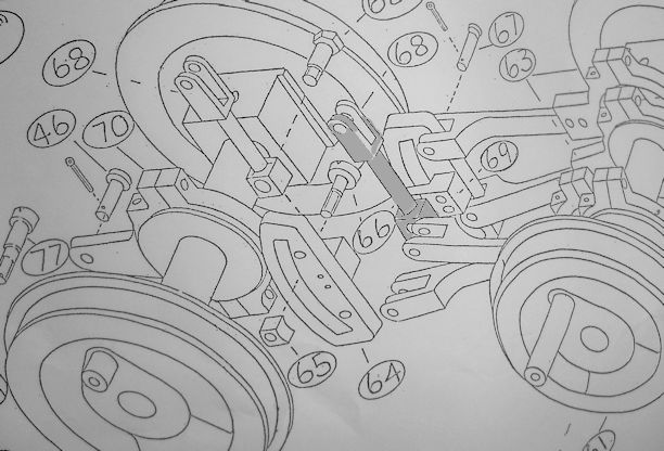
The instructions seem a little complex but when one refers to the supplied drawings it makes more sense.
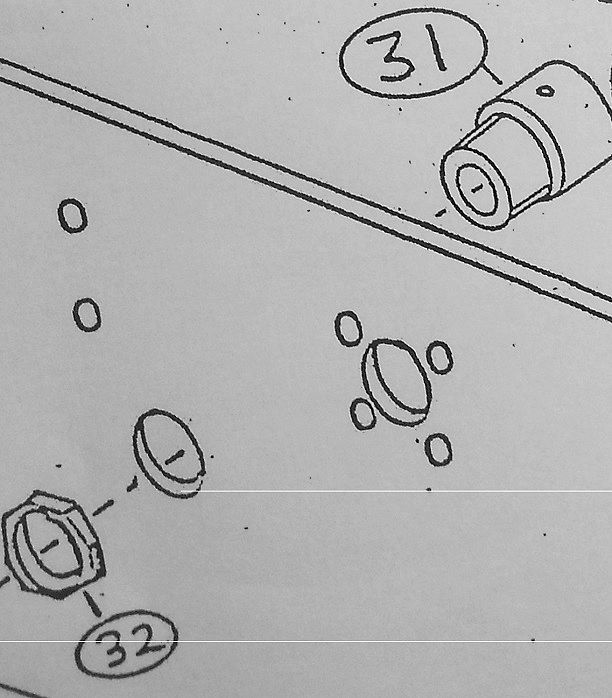
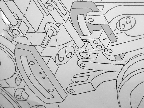
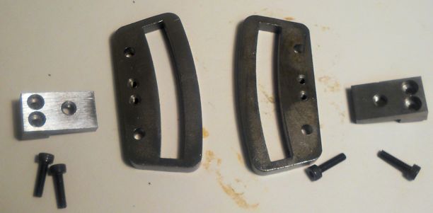
The parts in question are components 53, 54, 31 and 55.
The diagram indicates that the parts 53, 54, and 55 form the Complete Rocker Assembly.
The part 53 has instead of a grub screw to hole it on has a split part which is held tight by a clamping Allen Bolt.
Similarly with part 55 it too has a slit and clamping bolt.
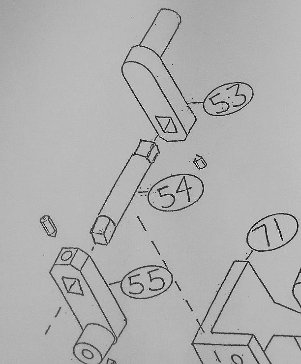
Part 54 is the bar at the centre which is very nicely made with square ends so that it is locked into a position.
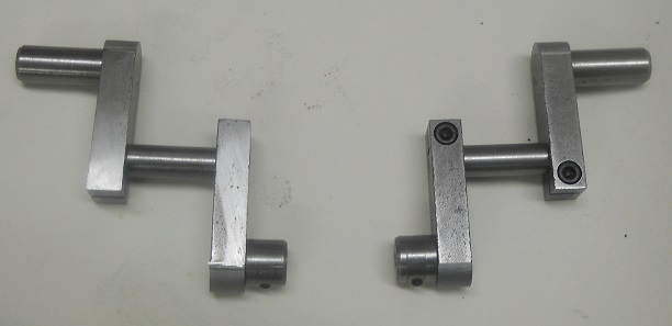
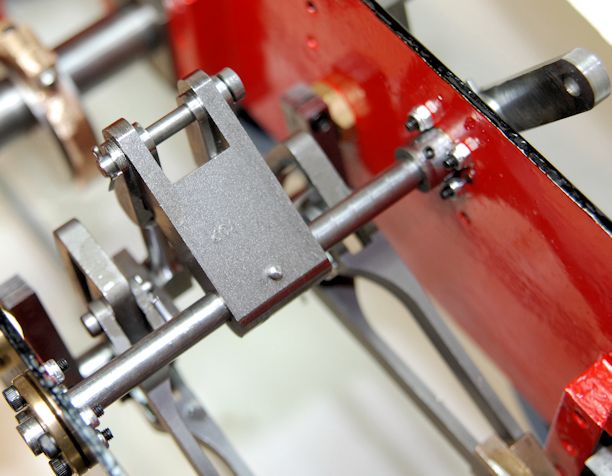
The left hand one is also now in place.
10th April 2017
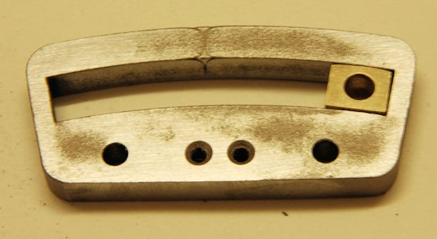
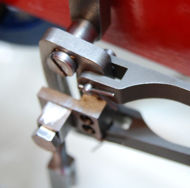
Whilst preparing the loco for it annual steam test it became apparent, whilst running on air, that the was looseness in the rocker and looking closely the nut Part 32 had come loose allowing the parts to not be aligned and in fact fouled the connecting rod and brought the engine to a stop. It was apparent that movement had occurred as the squared end on one side was nearly half way through the part.
How had this come loose. Well reading through the web site I made no mention of using a nut retainer which should stop such movement.
Some brake cleaner and Loctite Nut retainer medium strength was purchased. The clean up needed the parts to be completely removed so the two Allen bolts were released and all the parts taken off the loco and thoroughly cleaned up. The retainer was applied to the thread and the nut tightened up ensuring that the "OIL" hole was uppermost.
The remaining parts were then replaced and also tightened up.
A check round all the nuts and bolts on the valve gear was made and as appropriate tightened up.
The loco was given a quick run on Air and then left so that the Retainer could fully develop its strength.
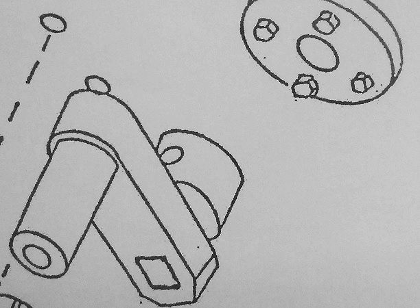
Attention is now turned to the valve gear.
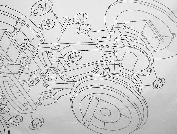
This is formed by 4 eccentrics strap parts 63 operating on Expansion links parts 64.
It is important to note the the upper eccentric arm goes to the outside nearest the frames on each side.
With mine I found one set did that perfectly but with the other a very slight adjustment was needed by putting the strap in my vice and then bending very gently. The error to adjust out was about 2 mm. but now both sets sit fine and are ready to be checked for burrs and then installed.

The wheels are certainly more difficult to turn round now but then I am not using the force that the pistons will use !
The build instructions indicate that the slot must be smoothed up obviously to make the Die Blocks operate in them easily.
The die blocks have to be filed to fit. it says "The long side concave and the other long side Convex." I am glad I have a digital micrometer to be able to identify the long side as they seem nearly identical.
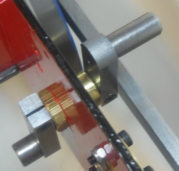
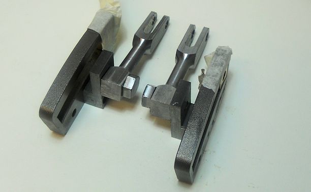
The inner surfaces of the Expansion link needed quite a bit if wet and dry to bring the surfaces to a smooth state following production as was suggested in the build instructions.
The photo shows the unprepared surface
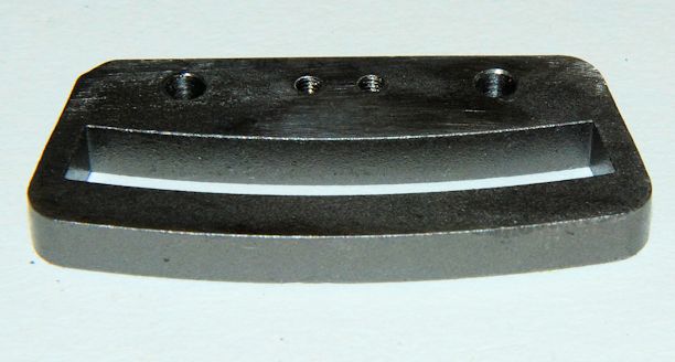
This took about a hour of careful filing and the use of wet and dry.
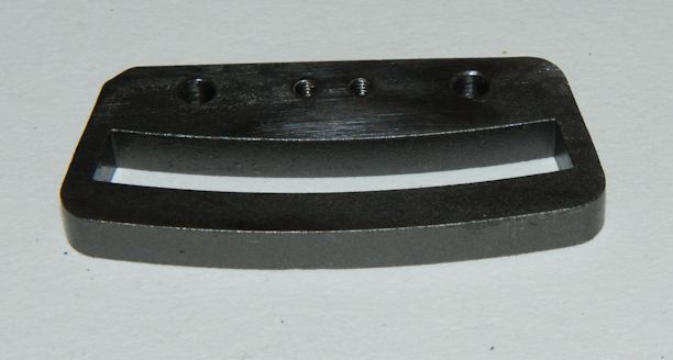
Measurement indicated that about 0.5mm off the width, so I started by bringing the top curve to shape and then filed the bottom flat so that the ends would just fit in the slot and then made the underside curve and finally adjusted both top and bottom to a nice sliding fit.
I must say that this part took a lot of time but well worth the effort as a sliding fit and not a slack fit is required.
I did find that after washing my hands that I had worn away some of the skin on my thumb something I will avoid when doing the second die.
Making the second die block was much easier. I first started by placing the blank on the top of the expansion link aligning the centre so the the end edges protruded about the top and then use the link shape as a guide to file.
Then the bottom was filed until the end just went onto the slot and then final adjustment was made by first filing away the centre of the bottom curve using emery cloth on curves file.
Very often checks were made to make sure where the removal of material was required.
It was all done satisfactorily in about 30 minutes.
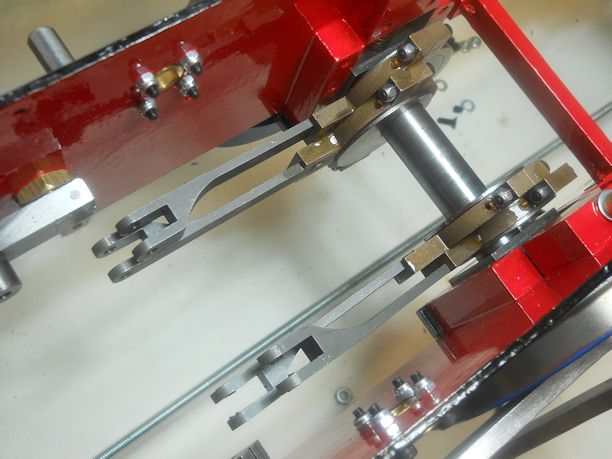
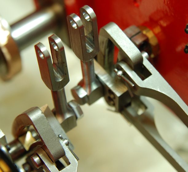
Sorry about the out of focus picture but the Trunnion Brackets have not been fitted to the expansion links.
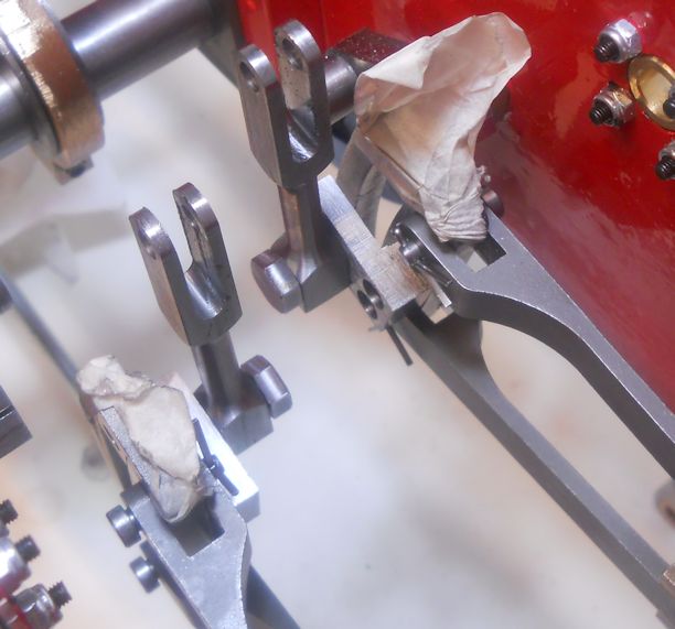
On the left hand side to the loco the two arms parts 69 had too small an opening by 0.3 mm so a few swift file passes and they were brought to size.
All the split pins have been inserted but now I have to locate a cutter to shorten then to about 1/4".
The tape is still there to ensure the die blocks stay in place until fitting is completed.
Now is the time to fix into place the die blocks. The piece of sheet steel that was mentioned in the build instructions was missing but soon substituted by a piece from the workshop. The Screw holding the Die Block in the expansion link was fully tightened up.
NB I have not yet cut shorter the split pins!
A small amount of oil was applied and a check was made that everything moved as I should.
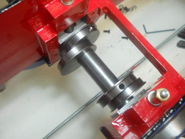
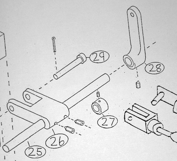
So part 28 does not need to be slid onto the shaft.as it is there already with its taper pin in place.
I do need to remove part 26 so that the 1/8" collar can be slid on and up to the arm part 28.
With that done the Weighshaft can now be pushed through the Right Hand side Weighshaft Bearing and the large Weighshaft collar part 27 slid on.
Then part 26 needs to be slide on and fixed.
So other than fitting the buffers which I am not ready to do as the loco is not yet on its wheels KIT 4 is no completed