|
||||||||||||||||
|
||||||||||||||||
| 27th August 2008
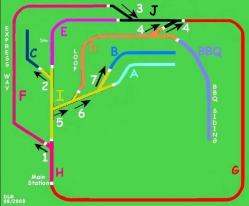
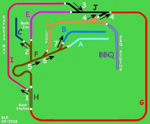
A start has been made on the isolation of track sections so that a "BLOCK" system can be employed to isolate sections. So far "A" "B" and "BBQ" were installed before today. Today I was able to install the isolation between the two points "4" and just after point "6" on the "Loop" side section "D". Also siding "C" was fitted with isolation. New cabling will be installed to feed section "J", with a power linked to section "D" the LOOP, and the wiring to make the "D" and "C" operational. |
|
|||||||||||||||
| As far as the actual circuit
is concerned the isolation at A B C and BBQ will all link to the track
ahead.
So A is linked to IF, B linked to I, C linked to I, BBQ linked to D. Independent power will be linked to D E F G H I and J |
||||||||||||||||
| 27th August
2008
All the isolation switches are now in place and all the wiring to the track completed and tested. This now means that an electric loco can be stopped and isolated in any of the b locks A B C D E F G H & I. Plans are now in hand to have a mimic board to show which sections of track are live by the use of 3mm LEDs. |
||||||||||||||||
| 31st August 2008
The final plan of the points was drawn up to represent the track a little better especially in the area where shunting can take place - A B C D E I and BBQ. As section I can have power applied independent of the other and the siding A B and C link direct to I, the sidings will ONLY be powered if I is powered. |
|
|||||||||||||||
| 2nd September
2008
Completed the full isolation of sections A B C D E BBQ & I from J & H. This means that shunting can take place on the section A B C D E BBQ & I by using a second speed controller and not interfere with the running round the outer blocks F H J & G. Consideration has been given to how high the tunnel clearance needs to be to cater for all "G" Scale locos and carriages and trucks. Research shows that most locos are about 175 to 180mm above Rail head but some American style locos may well be a little more. As I have the space I am going to use 210mm as my MINIMUM height ARH and this also agrees with recommendations of the "G" Scale Society. To this end I hope to soon build a loading gauge to be set of the exit to the sidings to double check each train as it leaves. |
||||||||||||||||
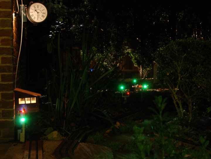
| 9th September
2008
Installed about 20 meters of low voltage supply and return (+ & -) to light most of the remaining Signal lamps. Pushing the cable through the slots in the decking was much harder work than for the pneumatic pipe which when pushed though had pressure on to blow out of the way and dirt!!! Five more of the signal LED's were installed and below is photo taken at night. In the photo is the station clock mounted on the wall, the signal box with interior illuminated and seven signals illuminated showing quite clearly the stop (red) and clear (green). The signal acetates are illuminated by an LED each running off a 9 volt DC supply. |
||||||||||||||||
|
||||||||||||||||
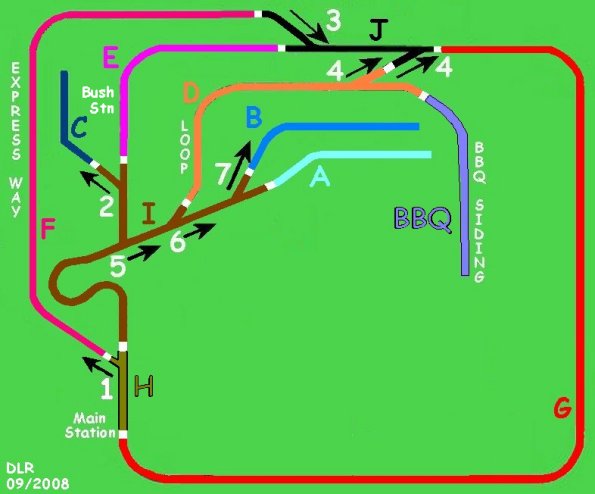
| 18th September 2008
The final design of the signaling board has been created and now a mimic board with LEDs shows which parts of the track are power.The significant difference is that track I and F have been swapped round so that the outer track is G H I and J making it much easier to set. |
|
|||||||||||||||
| The story continues | ||||||||||||||||