|
|
|||||||||||||
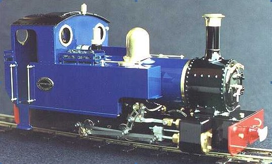
The building of ROUNDHOUSE LOCO"Lady Anne"the picture on the left is from the Roundhouse Web site .... the one below on the right is the finished version of mine !!! |
|||||||||||||
|
|
|
||||||||||||
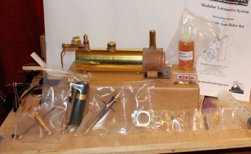
| Sunday the 28th October
was the day I decided to open
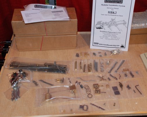
my Christmas present of 2007. A ROUNDHOUSE kit 45mm G scale
locomotive.
The very first thing I noted was how very well packed the delivery box was. Secondly when I open HBK 2 the first box marked Chassis kit I again saw how well packed the parts were in individually sealed plastics strips packaging and also I was supplied with a set of BA spanners. The instructions explains it does not pay to work to close fits in certain areas and this is what I found to my cost when building a 5" gauge loco as it bound up on the track and took a great deal of running in. Following the instruction I checked the packets against the listing and marked accordingly. There 8 packets which I marked A - H. Throughout the construction I am going to count the number of parts used. This will include a bolt and nut as two parts and the text will be annotated as parts are used.
|
|
||||||||||||
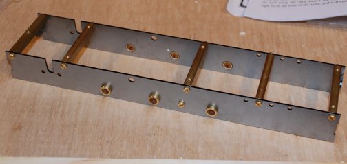
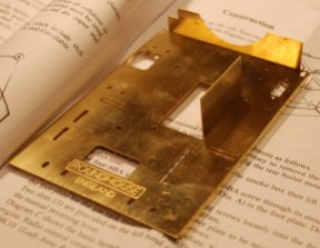
| The brass screws from pack D
were placed in a small screw top jar leaving all other parts in
the pack.
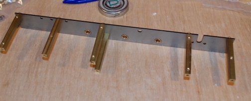
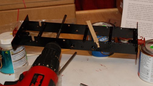
The spacers from pack C were removed ready for use leaving all other parts in the pack. There are six spacers. The frames from pack A were removed ready for use, the buffer beams and push rod were left in the packet. Part count 4. The spacers were fitted to one side as indicated in the instructions. To ensure that the spacers lay inline with the frame when the screw was tightened the frame and spacer were held against a flat piece of timber. |
|
||||||||||||
| The other side of the frames
was also attached and supported on a second piece of wood to
ensure both sides were parallel.
Part count total 16 |
|
||||||||||||
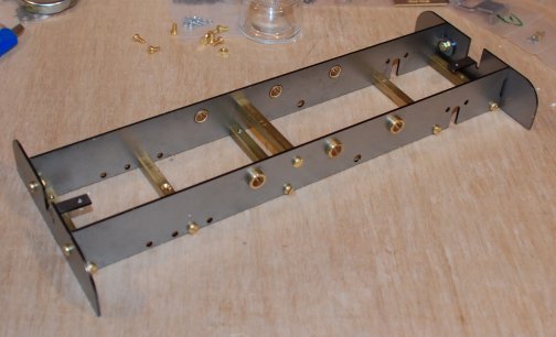
| Rather paint the frames now
I decided wait for that until after the buffer beams were in
place.
The M3 x 0,5 nuts were removed from pack D and added to the M3 pot. The buffer to one end was fitted and the nuts and bolts tightened with the frames and buffer flat on the building board to ensure squareness. Part count total 24. |
|
||||||||||||
| The centre buffers were
removed from packet D and fitted to the buffer beams.
Part count total 34.
|
|
||||||||||||
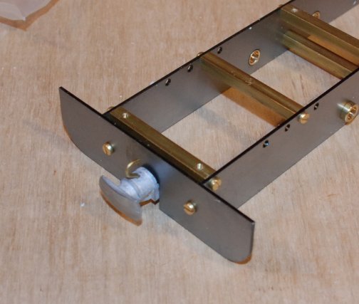
| Degreasing was carried out
by washing the assembly in the sink and then dried with a hair
drier. How wrong this method was!! Oil still remained but at
that moment I did not know.
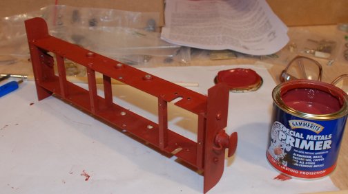
For the primer I decided to use the Hammerite Special Metals Primer as not only is the steel but also brass to prime !!! the tin was well shaken and then some decanted into a small jar. Checking the instruction it indicates that brushes are clean in "WATER"! The lack of proper de-greasing was over come by the use of Spectra de-greaser resolved all the oil problems. The next lot of primer went on like a dream .. |
|
||||||||||||
| After a 2 hour wait the
first coat of "SMOOTH" Black Hammerite was applied and now the
wait for 4 hours so that the second coat can go on!!!
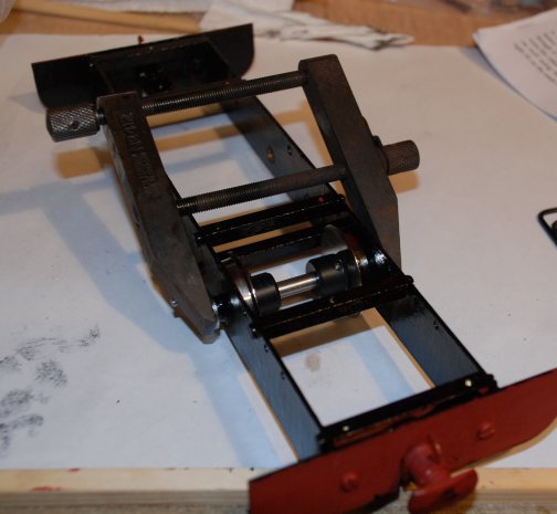
So with the second coat of Black paint complete it was left to dry overnight. Monday 29th October 2007 Day two of the construction The paint has dried well so the next stage is to clean off any paint that has gone into the bearing for the axles. First I used a wooden stick to clean out the majority of the paint then a piece of 1/4" bar coated in oil and attached to a battery drill. The bearing were soon running very easily and true. The three axles were removed from Pack "C"”. Lightly oiled and slid into the bearing. Part count total 37. I then removed the axles and pushed a piece of kitchen roll through the bearings to remove the oil and any last vestiges of paint. It was quite surprising how much paint deposits came out with the oil. |
|
||||||||||||
| The wheel were emptied from
packet "H"
Part count total 43. The instruction indicate to start with the rear wheels. The two cranks with the with crank pins fitted are removed from pack "C" Part count total 45.
|
|
||||||||||||
| Next the front axle and two
cranks from pack "C"
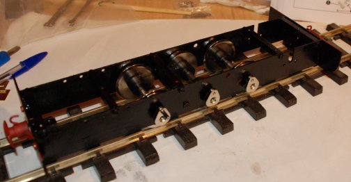
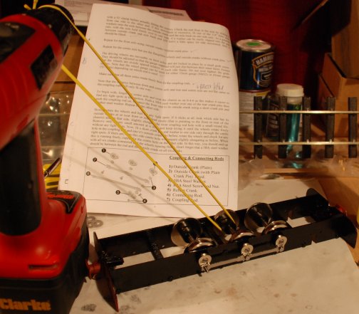
Part count total 47 Lastly the centre axle and two cranks from pack "C" Part count total 49. Then wheel gauge was removed with the Allan key from pack "C". The wheel sets were gauges to the 45mm track with equal spacing each side and equal side ways movement. The sets were checks for free running and all were free. A piece of spare track was brought in from the garage and the loco chassis placed on it to again check the gauge. A perfect fit. The six counter sink screw were removed from pack "D" and fitted to hold the crank tight. Part count total 55, |
|
||||||||||||
| The eight 5BA steel washers
were removed from pack "C"
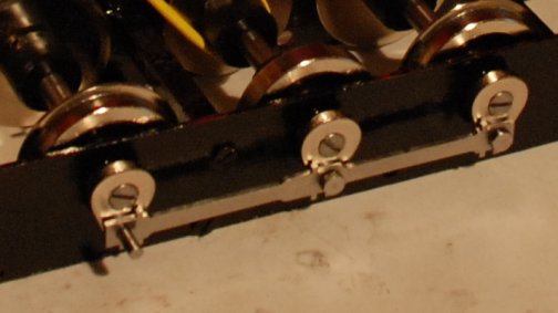
Part count total 61 The four short crank pins were removed from pack "C". The connecting rods were removed from pack "C" and one fitted to the front and rear wheel cracks on each side. The tight spots were eliminated by elongating the hole one the side where is bound at full forward or rearwards. The centre cranks were then connected and similarly elongated as necessary. I set up the battery drill and a piece of heat shrink as a band and was able to run the wheels until I was satisfied that the best was achieved until final bedding in is achieved. |
|
||||||||||||
| From pack "F" the four cap
screws and four washers were removed
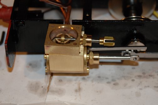
Part count total 69 From pack "F" the two cylinders were removed. Part count total 71 The left hand cylinder assembly was mounted first with the exhaust pipe bent out of the way. |
|
||||||||||||
| From packet "F" the slide
valves were removed.
Part count total 73 The slide valve was placed on the steam chest. An "O" ring was removed from Pack "F" and placed on the steam chest. One of the valve chests was removed and placed on the "O" ring Part count total 74 Two of the counter sunk brass screws were removed from pack "F" and one of the valve chest covers. Part count total 77. The valve chest cover was fitted to the out side.. Similarly with the other valve chest Part count total 83. As the other brass counter sink screws kept falling out of pack "F" the eight were put in my pot marked "D". Part count total 91 |
|
||||||||||||
| The instruction now say "if
using the ROUNDHOUSE HBK4 boiler kit removed the super heater
tube".
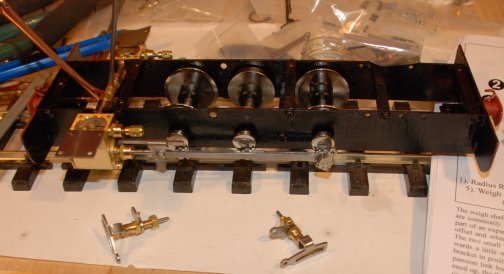
Part count total 92 In the fitting on the super heater are the two "O" rings needed to fit the inlet pipes. These were found inside the fitting. The right hand cylinder was removed and the left one fitted to the super heater. The right hand cylinder was then re-fitted to the chassis and to the super heater. The pack HBK 4 was closed up again. Tuesday 30th October 2007 Day three of the construction The two connecting rods were removed from Pack "C". The two Cross heads were removed from pack "F" with the two cross head retaining bolts. Part count total 98 These were both fitted - but it took some while to realise I was trying to put them on the wrong way round !!!! Also it was very difficult to see the cranking in the connecting rod. Still eventually I did do a good job. From pack B the return cracks were removed together with a pair of nuts and bolts and thirteen 5BA washers Part count total 117 Both return cranks were fitted. The two weight shaft brackets and two expansion link bushes were removed from pack "B". Part count total 121 The weight shack brackets were bent as directed in the instruction and fitted to part of the expansion link. The weight shaft was removed from pack "C" and straightened so that the straight edges were fully in line along a straight edge. The right hand side weight shaft bracket was fitted. Three star washers removed from packet "B" Part count total 124 Fitting the star washer was a difficult task but once the start have been made the washers mover quit easily.
|
|
||||||||||||
| The two Eccentric rods were
removed from pack "B" together with seven shouldered crank pins
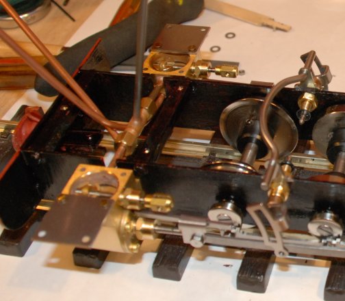
Part count total 133 They were then fitted and the position of the return cranks checked as far as possible. Two radius rod were removed from pack "B". Part count total 135 Two shouldered crank pins were prepared to act as the slide blocks. The left hand side one was fitted first then a pair of steel screws were removed from pack "F" and one fitted to the valve linkage. Part count total 137. Wednesday 31st October 2007 Day four of the construction From pack "B" I removed the two lifting arms - a left one and a right one. There is no sign of the spacer mentioned in the instructions so I will have to email and check this out. Part count total 139 To fit the items I had to undo the Expansion link bush ( left and right) and allow the weight shaft brackets to roll forward and then I was able to slide on the lifting arm both left and right. Removed the two and four M2 bolts and four M2 nuts from pack "B". Part count total 149 The parts were fitted. The gear was locked in mid gear and the Alan keys locked on the swinging arm. Placing a piece of paper on the small section of track it was quite possible to make all the wheels move and thus all the valve gear etc etc. Tonight I am going to Machine Mart in the hope of buying a small compressor .. In preparation of running the chassis on air I established that the end of the superheater was ¼" x 40 ME thread so made up a suitable union to fit.
|
|
||||||||||||
| I was able to buy a very
small air compressor for paint spraying and with some neoprene
hose that I had linked up the chassis and the air was applied.
The reverser was set to reverse and the wheel went round immediately. After a few minute I stopped the air compressor and put the reverser into forward gear. Again the wheels went round beautifully. After an hour and 20 minutes the chassis ran on 4 psi !!!! After another 30 minutes the chassis ran on 3 psi !!! After another hour run the right hand crank went out of position. This we re-set and the valve position adjusted slightly. When the air was re-applied the wheels went round better than ever in both directions. Two of the roll pins were removed from Pack "B" and a 1.6mm hole drill which was opened out to 1.67mm and the roll pins pushed in. Part count total 151 A check on the air revealed the still the wheels went round well in both direction. |
|
||||||||||||
|
Thursday 1st November 2007 Day five of the construction The spare parts from all the packs were emptied into a glass jar marked "D". That then left pack "E" which is the reversing lever. As the footplate provided the mounting for the reversing lever this pack was left intact. But first to locate the foot plate from the Body Kit HBK6 . Part count total 152 The foot plate was removed and bent as instructed . This afternoon I will be visiting Jack Ruler and use his sand blasting kit to clean and key the footplate in preparation for painting. So after a tidy up of the work bench it is onto HBK4 Lady Anne Boiler kit. |
|
||||||||||||
|
|
|
||||||||||||
|
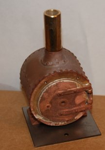
The following parts were located as needing painting NOW !!! The floor of the cab -- The smoke box -- The outer wrapper of the boiler. Part count total 155 The two bolts - part of the wrapper were put in a jar for safekeeping marked "BOILER". |
|||||||||||||
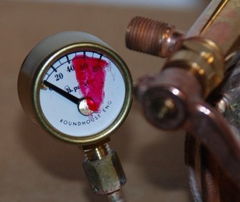
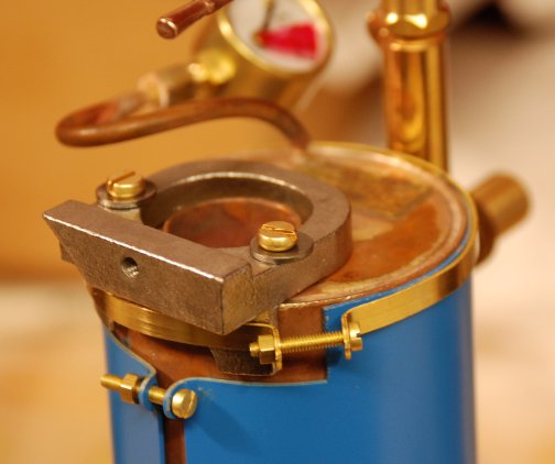
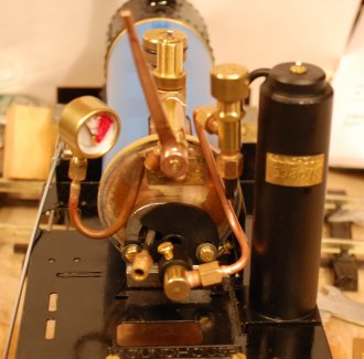
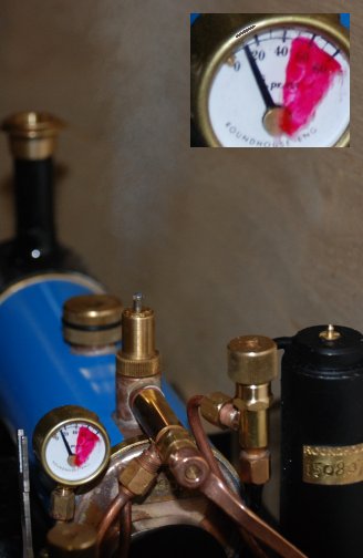
| The instructions indicate
that the safety valve blows at 40psi so I have suitably marked
the face of the glass with red nail varnish at the 40 and
covering the top part of the range.
The sand blasting with Aluminium oxide was a great success. I hope to sort out a spray booth tomorrow and then paint the items. The parts sand blasted were also given a wash over with the de-greaser. The loco chassis has so far run for 10 hours - on air - and seems to be very smooth forwards and backwards. |
|
||||||||||||
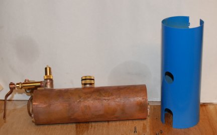
| Between the 1st November and
11th November Say 4 days of construction
I have been able to make up a simple spray paint booth and a heated drying cabinet all very simple ply construction - but it does the job. The loco has now run for 15 hours forward and 10 hours in reverse. The outer wrapper of the boiler has been sprayed with special etch primer and then a day later acrylic blue paint. The smoke box was also give a coat of the etch primer and then heat resistant black paint. First coat hand painted and second coat I ventured into spray painting with a Badger 150-1 Spray paint unit. I am pleased with the results. |
|
||||||||||||
|
|
|
||||||||||||
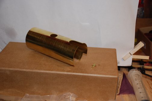
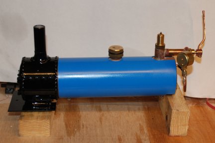
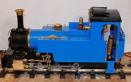
| The outer
wrapper of the boiler has been sprayed with special etch primer
and then a day later acrylic blue paint. The smoke box was also
give a coat of the etch primer and then heat resistant black
paint. First coat hand painted and second coat I ventured into
spray painting with a Badger 150-1 Spray paint unit. I am
pleased with the results.
Putting the boiler wrapper back on was an effort until I read in the diary that I had put the wrapper bolts and nuts in a jar marked "BOILER". Once found the wrapper went on easily.
|
|||||||||||||
| The position of the smoke
box and the steam outlets were assessed and bent accordingly.
The "SUPERHEATER" tube was bent over a 11mm bar of stainless steel. The smoke box was fitted with three brass screw from pot "D".
|
|
||||||||||||
| From the Pack "B1" an 8BA
bolt and nut were removed .
Part count total 156 The boiler mounting foot and the boiler bad were located and removed from packing. The ends of the boiler band were bent at a suitable angle ready to accommodate the 8BA bolt and nut to hold the boiler foot in place. The boiler was stood on two blocks of wood and a check for squareness made. With all looking fine the boiler band was tightened up. Having the HBK Body kit the floor had previously been painted and was now ready to be fitted .
|
|
||||||||||||
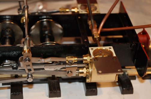
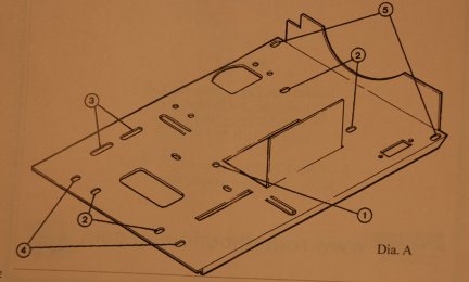
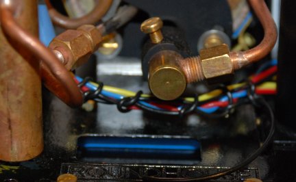
| The instruction in the Body kit were followed and the diagram shown used. However it was found that the bend in the super heater was insufficient so the whole of the smoke box had to come off again and the superheater re-bent to accommodate the end of the boiler. |
|
||||||||||||
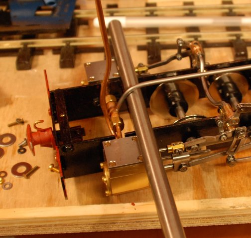
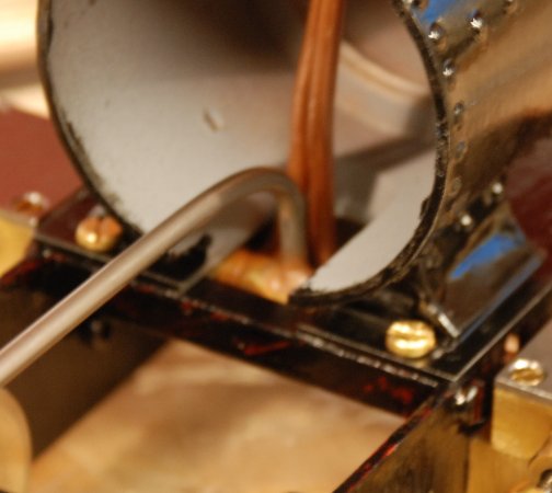
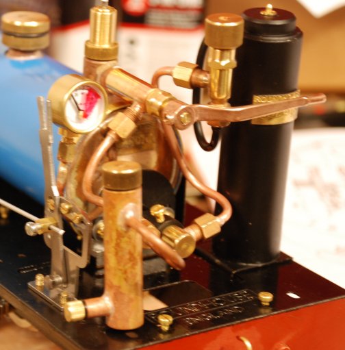
| The picture shows the tight ensemble of pipes in the smokebox. |
|
||||||||||||
| Then 4x 6BA screws were
removed from pack "B1" and used to loosely hold the foot plate
in position.
Part count total 160 I can see no instruction to fit the front boiler band so I am going to fit it now !!!! The 8BA bolt and washer was removed from pack "B2" and a nuts from pack"B1" and the boiler band located.. Part count total 164 The band was fitted. |
|
||||||||||||
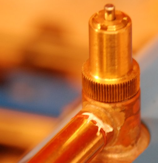
|
The next stage is to give attention to the correct fitting of the regulator. The fibre washer had to be reduced in thickness and it now ready for the regulator to be finally fitted using PTFE tape. Some PTFE tape was recovered form my steaming box for the 5" loco and a piece wound behind the Fibre washer. The regulator was then tightened up so that the outlet was in the 7 "o’clock" position looking from the rear.
|
 |
||||||||||||
| It was at this stage that I
noted that the smoke box door did not have its door handle
fitted so off with the boiler and smokebox again .
The handle assembly was removed from pack "B2" and fitted Part count total 165 The hand rail knobs were removed from the pack "B2" and hand rail. And fitted Part count total 168
The chimney top was removed from pack "B2" and fitted. Part count total 169
Monday 12th November 2007 Day 11 of the construction
The burner was located and removed from the packing and fitted. Part count total 170 The gas tank was removed from the packing and fitted Part count total 171 The gas pipe to the burner was removed from the packing, bent to shape and fitted. Part count total 172 |
|
||||||||||||
|
The lubricator was removed from the packing and fitted Part count total 173
The reversing lever was now removed from the packing assembled and fitted. Part count total 188 I found that although the instructions said to put the connecting rod on the inside this then greatly fouled the pressure gauge so a compromise fitting was achieved with the reversing base as per instruction but the lever on the outside.
|
|
||||||||||||
| Body works
I had sprayed most of the body panels before I realised that they had to be soft soldered in places. I have arranged to go and sand blast the items tomorrow but tonight I thought I would see how much there is to soft solder and I will not know that until I have folded up the parts. So first out were the two main sides of the body work Part count total 190 These were bent up and it seems that only a very little soldering if necessary. Next was the front of the body work Part count total 191 Again not much soldering here so all cleaned off with a file. Next was the rear of the cab. Part count total 192 Again only a few small solder joints. I was able to solder all the parts together using my very large electric soldering iron usually used for Stained glass construction. Job completed in about 3 hours. I then de-greased the body shell ready for painting. |
|
||||||||||||
| Tuesday 13th November 2007 Day
12 of the construction
I was not able to get the sand blasting done on the loco until late in the afternoon so decided to give the loco its first run under steam. Preparation for steaming was made in the garage - too cold to be outside. The Steam oil was topped up the boiler filled with water then 30ml removed as per the instructions and then the gas tank was charger. The loco was put up on blocks and the gas turned on .. No obvious leaks of gas / water nor oil, so light the gas. A nice pop was heard and the burner roared into life. Very quickly the pressure gauge read 20psi and the safety valve blew. I do not know if it is the valve set wrongly or the pressure gauge is off calibration. Email has been sent to "Roundhouse" and I await their reply. Forward and reverse gear was checked .all ok so it was out to the track. At 16:00 the loco made it first run under steam and worked well forwards and back wards The cab was sand blasted at 17:00 and de-greased and put in the "warm cabinet" until tomorrow when the spray painting will commence.
|
|
||||||||||||
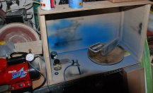
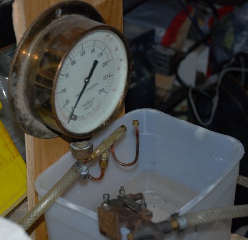
| Wednesday 14th November 2007
Day 13 of the construction
Check was made of the pressure gauge on my primitive but sufficient equipment and this revealed that the gauge is fine. |
|
||||||||||||
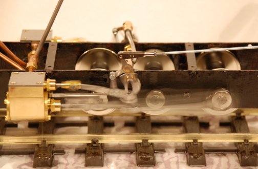
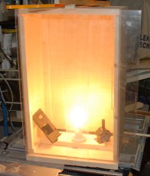
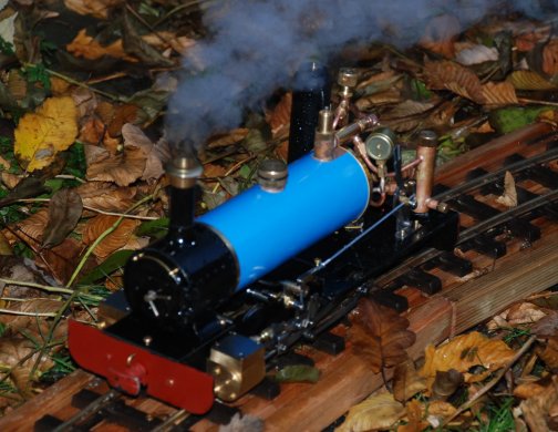
| Here is the loco under steam
and the safety valve venting at under 20 psi where as the design
is for 40psi. I have contacted ROUNDHOUSE and am awaiting a
reply.
The body work has been spray painted and currently is drying and harding off in the warming cabinet. |
|
||||||||||||
| Thursday 15th November 2007 Day 14 of the
construction
Very quick reply from ROUNDHOUSE advised "The safety valve is adjustable by means of the centre collar with a slot at either side. Screw it down (clockwise) to increase the lift pressure. We do put a small dimple in the side of the body to prevent the collar moving on it's own, but you can still adjust it, it just makes it a little stiffer. The valve to boiler bush thread is 5/16" x 32 ME. Speaking to an amateur radio friend who deals with industrial boilers I was told "Do the initial test on water and not air". So I made up a "key" to be able to screw down the collar and also an adaptor for the water pressure test set up, to take the boiler bush thread is 5/16" x 32 ME. Under test I screwed in the collar until the water was released at what I thought was 40psi but running the loco on steam revealed a release pressure of 35psi. A re-test in the water pressure set up confirmed a release pressure of 35psi. I am going to stay with that level for at least the running in period. |
|||||||||||||
| So after all the tests on
the loco and its pressure gauge is has now returned to the work
bench in doors.
The cab roof was located and the hinge together with two 8BA counter sunk nuts and bolts. Part count total 200 The hinge was bent up and fitted to the roof.
|
|
||||||||||||
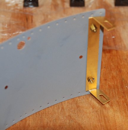
| I am now to take a look at
the RADIO CONTROL parts and see what needs sandblasting prior to
painting. The pack is extensive.
I have located the "Dummy Roof Vent" and it need to be painted and there are fold lines so also needs to be bent. The roof was suitable bent. Part count total 201 The two pillars for one of the servos were removed as they two will need to be painted. Part count total 203 The support for the other servo is a brass plate that needs bending and painting and prior to that two 6BA screw solder into place Part count total 206
To achieve the soldering I used my micro flame torch and found that it was much easier than with the electric soldering iron. Having had one of the lugs on the body work break I decided to "beef up" the bend of the bracket where it holds the servo. So this too can now be sand blasted.
|
|
||||||||||||
| The three coal bunkers were
located and bent to shape and soldered and the two lamp brackets
fitted and soldered into place - however I found trying to soft
solder sand blaster parts very difficult.
NOTE: Next time assemble first then sand blast then paint !!!! Part count total 211 |
|
||||||||||||
| Friday 16th November
Day 15 of the construction
An early start and sandblasting of the remaining parts. Then the etch primer was applied and after a few hours drying the top coat was applied in two layers. So the start of the final section of the construction of the cab. Fitting all the hand rails with 8BA nuts on the fitting Six hand rails were removed from the packing and 16 bolt fitting and nuts Part count total 231
|
|
||||||||||||
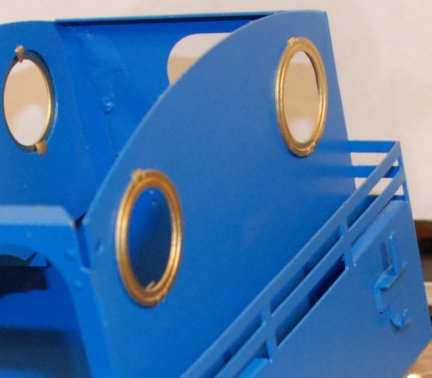
| The four spectacle brass
fitting were removed and fitted
Part count total 235
The roof bolts were amended as per the instruction and then soldered over . The roof is now ready for painting. So off to the workshop and spray the underside of the roof blue and the top side black. Also painted was the dummy top vent which is in fact the antenna for the radio control. |
|
||||||||||||
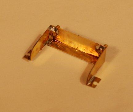
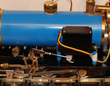
| Fitting the radio
control.
First to be fitted is the servo for the reversing operating of the Walschaert's Valve gear. The original linkage to the Reversing handle was removed. The first of two pillar support were fixed in place at the front and this was followed by the second one to the rear. Note they as NOT in line intentionally !!. Part count total 215 The output arm was attached to the reversing lever and the original linkage adapted to link to the weight shaft. A check on the transmitter revealed that all was ok.
|
|
||||||||||||
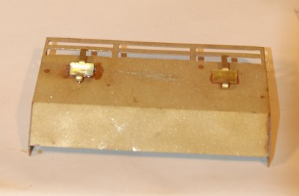
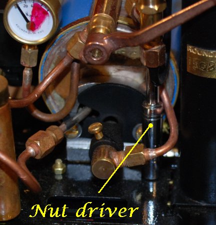
| Two more bolts and two
washers were removed from the packing and used to fit the servo
into place.
Part count total 217 As instructed the fixing bolts and washers were filed down to a nice snug fit between the frames. Fortunately I had a 6BA nuts driver else fitting the nuts to the bolts would have been very difficult.
|
|
||||||||||||
| The receiver and all cables were set in place and lacing cord used to tidy up the leads. |
|
||||||||||||
| So with just a few moree
hours work the R/C is fitted and the cab roof is on the antenna
plate is fixed and here she is less dome.
The water filler caps have still to be fitted and also the coal stores on the side tanks but it is now charging its batteries ready for a first R/C "shake down" run tomorrow. |
|
||||||||||||
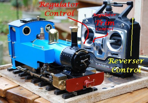
| Saturday 17th November Day 16 of the construction
So here she is ready to fire up for her first run under Radio Control for the Reverser and Regulator. The regulator control is in the standard position left hand stick up for increase and down for decrease. The reverser control I have put on the rotary control as I find it easier to operate and it is out of the way whilst running. Such a control may only be found on a 6 channel R/C set such as the one I bought. The only problem I had to enable her to run was that I had set the regulator too much closed and this had to be adjusted to allow steam to pass. Once adjusted ....... well see below. |
|
||||||||||||
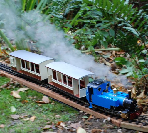
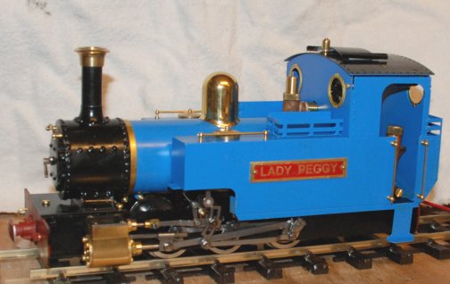
| So here is "Lady Anne" as
per "ROUNDHOUSE" name but now know by me as "LADY PEGGY" after
my late mother who would have loved to have seen the track and
loco.
Lady Peggy is on her first ever run under R/C and performed faultlessly. The main regulator control was hardly used at all as the regulator trim control gave all the control required. Of course the load on the loco was very small and in time more coaches will be added. The run lasted second time about 30 minutes and might have been longer if the gas had been turned down more and less steam lost through the safety valve !!!! A big thank you to "ROUNDHOUSE" for provided the availability of such a great kit. |
|
||||||||||||
| Tuesday 20th November
Day 17 of the
construction
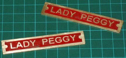
Using a process which was outlined to me by a friend of mine which together with my self are members of the Maidstone Model Engineering Society. It involves :- a spray can of photo resist, graphics made on clear acetate, a UV exposure box, an etch tank, and brass sheet cut to size 15mm x 75mm I have been able to make up the name plates for "Lady Peggy". I shall be attaching them with 1/16" brass rivets to the side tanks of the loco. |
|
||||||||||||
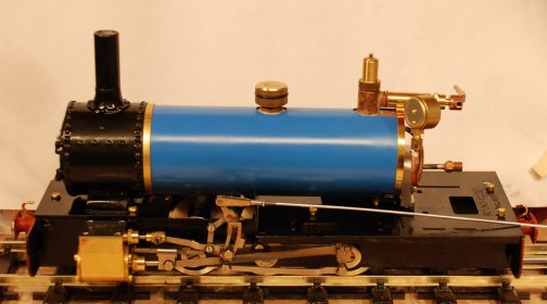
| So here she is "LADY PEGGY"
complete with name plates fitted.
I have ordered a few extras which will be added in due course but as far as the basic kit goes you see it all in front of you.
Link to video clip. |
 |
||||||||||||
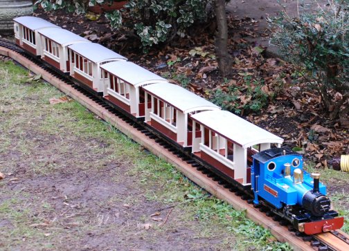
| Sunday 25th November 2007
Here Lady Peggy is ready to haul 6 coaches which she did with no derailments. |
 |
||||||||||||
|
|
|
||||||||||||
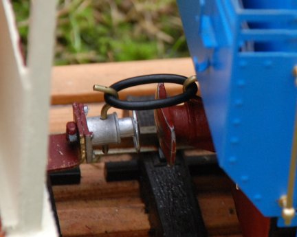
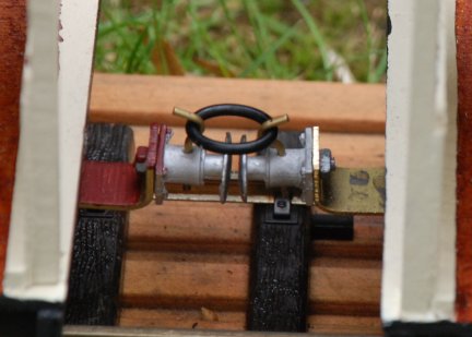
| In the train
above the linkage "experimentally has been changed from a 2 link
chain to "O" rings. The reason is that the coaches had been
de-railing when they went down a slope and bumped heavily into
the coach ahead. The use of the "O" has completely stopped the
de-railments cause by bumping.
The "O" have a little give in them and as the photos show there can still be a slight gap between buffers when pulling a large load the "O" ring stretches considerably and thus is hopeless except for lights of loads. The next experiment is to have fixed brass linkage so that the buffers almost but not quite touch. The brass linkage was a partial success but now a further development with an articulated linkage. More details soon . |
|||||||||||||
| Late
February 2014 The linkages are now based upon "Hornby OO" and as such are working very well. 26 FEB 2014 The loco was taken to my Model engineering Club and the re-test of the boiler carried out and a steam test and soapy water test on the gas tank. All passed with out problem. The loco have made approximated 150 runs in the last 7 years and is still performing very well. Later in 2014 I am to purchase a small Video recorder and hope to have some video to share on here of her running. |
|||||||||||||
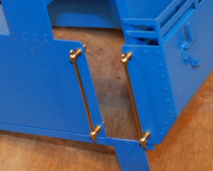
| July
2015 The radio control set has failed to pair between Tx and Rx so a new set is required. To make removal and refitting of the cab to the loco the two nut holding the rear part have been replaced with threaded bar and a cross cut so that a screwdriver blade can now tighten down the threaded bar in place of nuts. |
|||||||||||||
|
|
|||||||||||||