|
||||||||||||||||
|
|
||||||||||||||||
| 11th August
2008
Before you can consider how you are to arrange signalling you have to decide in how much detail you wish your signals to be compared to those on the "real railways". I have taken the view that I want signalling to be unambiguous and reliable such that if the signal says the line is clear then other than a points failure the line is clear. |
||||||||||||||||
|
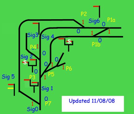
The next stage is to draw a detailed pictorial plan of your track and points and indicate the position of signals and their state by using 0 and 1. A "0" indicate that no active pressure in pneumatics or electricity in an electrically operated point is needed and a "1" indicates pressure or electrical signal. You can then develop a "Truth Table" for the system. In my system I am using pneumatics so below I have indicated how many pistons are required at a signal. |
|
|||||||||||||||
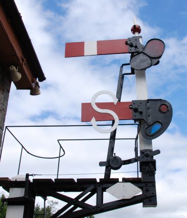
| I am also using an "S" signal which I first saw at Buckfastleigh South Devon Railway to indicate a siding and it was quite common in the early years for junction signals to have 'indexed' arms to make it quite clear to the driver that they were going into siding. |
|
|||||||||||||||
| Signal 0
Line side no attention required. Signal 1 Main Left and Right working opposite (ONE PISTON) "Y" frame higher on Left hand side for Main Needs P3 = 0 Main Left CLEAR Right DANGER Needs P3 =1 Main left DANGER Right CLEAR Signal 2 Double arm Main and S type (TWO PISTONS) "Y" frame higher on Right hand side for Main Needs 000 for Main arm = clear else danger so fit 2x OR gates fed from P4, P2 & P1a to feed the piston for main arm. S type arm needs 1 for clear from P4 so separate piston |
Signal 4
Double arm ( main type and S type) working opposite (ONE PISTON) "Y" higher on Left hand side for main IF P1b =0 then Main = danger S = Clear IF P1B = 1 the Main = clear and S = Danger
Signal 5 Double arm Main and Distant (TWO PISTONS) ARM set one above the other IF P2 = 1 then Main is CLEAR IF P2 = 0 then Main is DANGER IF P1a =0 then Distant is CLEAR IF P1a = 1 then Distant is Danger Signal 6 Single arm Main (ONE PISTON) IF P1a = 0 then CLEAR IF P1A = 1 then DANGER |
|||||||||||||||
| 18th August
2008
Installed the pneumatic operation for point P1a |
||||||||||||||||
| 19th August
2008
Installed the pneumatic operation for point P1b and also updated S6 and positioned it at the exit from the siding, just before P1b but indicates the same as if in the position between P1a and P2 as it is operated by pneumatically operated by P1a/P1b. Although this is incorrect when using the distant signal at Signal 5 as far as safe driving goes if the signal S6 is clear then it is ok to move over the points P1A. The two signals adjacent to the Signal box are now operational. |
||||||||||||||||
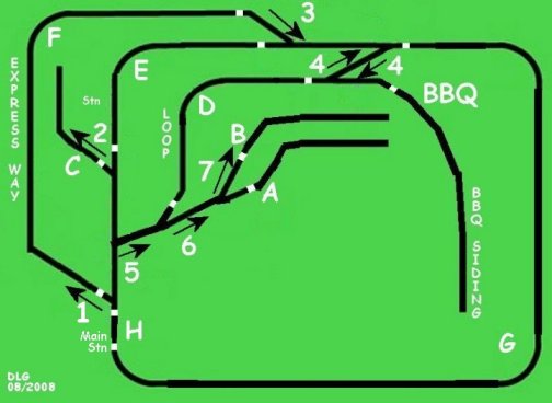
| 23rd August 2008
All points and most of the signals are now operational. The 25th of August will be the first anniversary of the DLR so today a BBQ was held and a new wall chart devised to assist with switching the points correctly. The points are numbers 1 - 7 and the arrow indicates when the pneumatic switch is throw the direct of travel. Letter A B and BBQ indicate the siding that have electrical isolation C is yet to be carried out. Future plans include providing BLOCK working in sections D E F G & H |
|
|||||||||||||||
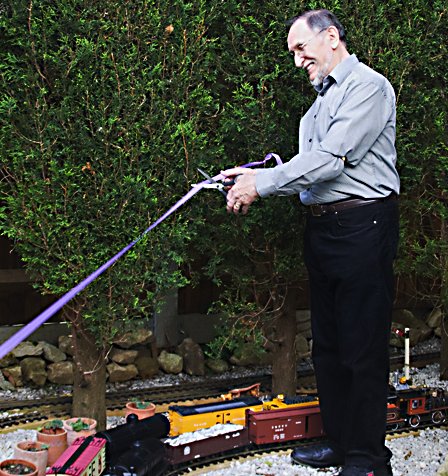
| 28th August 2008 The station of Kota Bharu which John constructed is opened by him. The photograph was taken by my amateur radio friend Trevor. |
|
|||||||||||||||
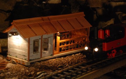
| The station at night. |
|
|||||||||||||||
|
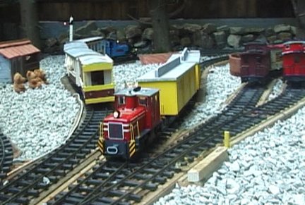
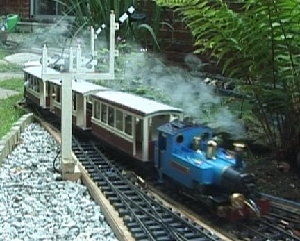
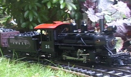
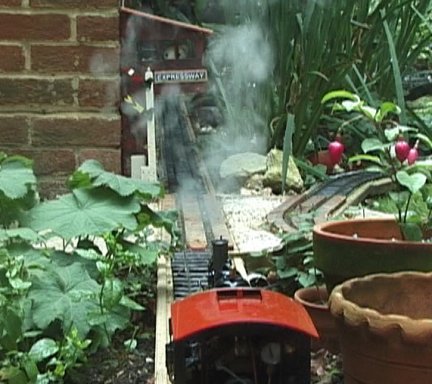
Below a few other photographs taken from the video of the BBQ |
||||||||||||||||
 |
 |
|||||||||||||||
 |
 |
|||||||||||||||
| Continued on next page | ||||||||||||||||