|
|
|||||||||||||
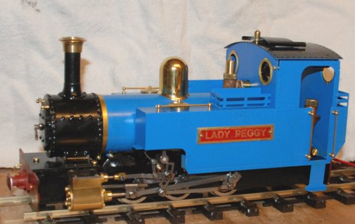
Track "SUPERELEVATION", Check Rail and"Lady Anne" now called "Lady Peggy" |
|||||||||||||
|
|
|||||||||||||
| Having had three
occasions when Lady Peggy has taken a roll off the track on the
sharp bends 600mm radius I decided to investigate the reasons
why.
It has to all be associated with the speed going round the bend and of course going too fast round the bend. Chatting to a scientist friend of mine he told me that I needed to find the Centre of Gravity of the loco and from there as experiments develop it will be possible to find the max speed around a bend of certain size before the loco rolls off the track. (Well not all associated with speed as will be found out at the end of this piece). |
|||||||||||||
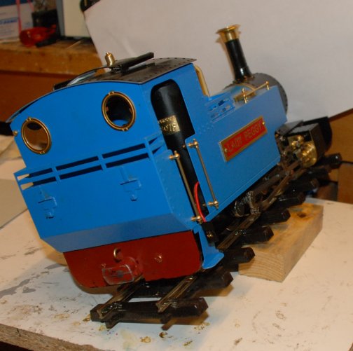
| He continued to say:-
The easy way to obtain a good approximation of position of C of G by reference to the rail head is to:-
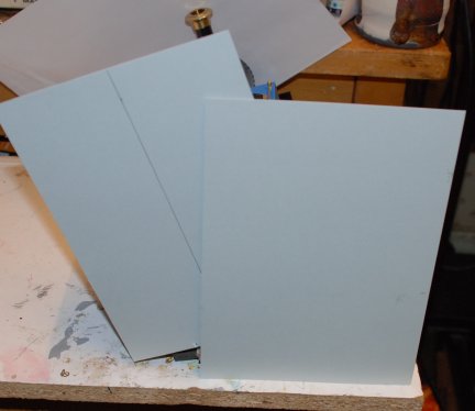
Set the loco on track that can be superelevated and held at the position of tilt where the loco just does not fall over. |
|
||||||||||||
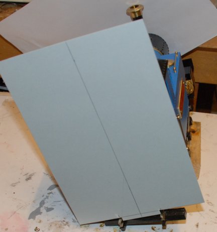
| Make up a card that fits
snugly between the rails. Mark on it a centre line through the
centre of the gauge to the top of the card.
Make up a card which has a know good right angle to be used to mark the original card.
|
|
||||||||||||
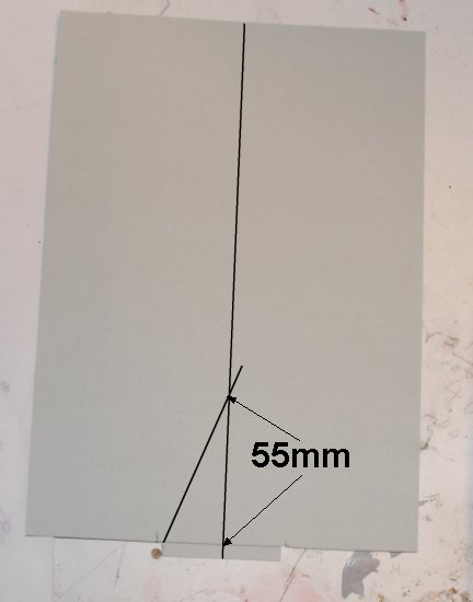
| Line up the second card to
the rail head inner surface and draw a line up to meet the
centre line drawn previously.
|
|
||||||||||||
| Measurement, on the centre
line, between the rail head and the intersection of the two line
will give a very good approximation of C of G."
So I did this and found that my Lady Anne is a C of G of 55mm with the boiler full of water.
|
|
||||||||||||
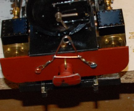
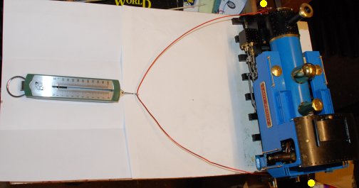
| Next it was suggested that I
used a spring balance held at the point of the C of G and with
the track level note the weight needed to start to lift the loco
off the track.
Two linkage were devised to attach the spring balance to the loco.
|
|
||||||||||||
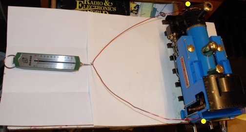
| The spring balance was
connected to the fixing points and a measurement made.
RESULT over 1 kilo gram. |
|
||||||||||||
| The spring balance was
connected to a higher fixing points and a measurement made.
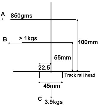
RESULT over 850 grams. |
|
||||||||||||
| The figures are shown in the diagram opposite. |
|
||||||||||||
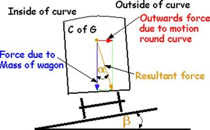
From here I
would like to thank a contributor, who sent me an email, for his
help in showing me the way to the understanding of the forces
acting on a loco both on a flat (horizontal) track
and a superelevated track
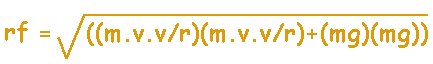
Firstly on a horizontal trackThere are 2 forces acting on a loco going round a bend:- The vertical downwards force due to it's Mass "m" and Gravitational pull "g", mathematically m x g The horizontally outwards force due to the Mass of the loco "m", the Speed it is travelling "v" and the Radius of the curve "r", mathematically m x v x v / r By Pythagoras these can be resolved into a single force the Resultant force From the triangle of forces: tan tan at the special case of the point of tipping over the resultant force will act through the c of g (c of m some say) and down through the outside rail, tan tan Thus v2 / r x g = 22.5/h hence v2 = 22.5 x r x g /h As this is at the point of tipping over the v = max speed before tipping is calculated to occur thus Vmax.
|
|||||||||||||
Secondly on a superelevated trackr = radius of track g = gravitational force h = height of c of g above the OUTER rail head in fact this actually doesn't make a huge difference! |
|
||||||||||||
|
|
|||||||||||||
| And now for some maths which
I hope is correct ..
Taking moments Loco weight 3.9kgs with boiler full. half width of gauge 22.5 the amount the C of G would have to move to topple the loco gives 3.9 x 22.5 = 87.75kg.mm Imperially I achieved :- at a height of 100mm 850gms (0.85kgs) which is close to a calculated amount 87.75 / 100 875gms which gives a moment of 0.850 x 100 = 85 kg.mm
at a height of 55mm greater than 1kg (I only have a spring balance that can achieve 1kg) which is close to a calculated amount 87.75 kg/mm / 55mm = 1.59kgs
|
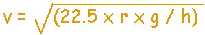
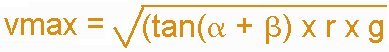
Then by calculation for
maximum speed :-
Vmax = SQRT(22.5 x r x g / h) ( equation given to me on the G1MRA forum) 22.5 (mm) is half the gauge (the down force has to move from the middle ie when stationary, to just outside the outer track edge to tip the loco over.) r is the track radius in mm g is the gravitational constant in mm / sec / sec; the value I used was 9728 h is the height of C of G My radius of track is 600mm and C of G is 55mm Vmax = SQRT(22.5 x 600 x 9728 / 55) mm/sec Vmax = 1545mm/sec Speed in mm / sec x 0.00224 gives actual mph. ( equation given to me on the G1MRA forum) Vmax = 1545 x 0.00224 MPH Vmax = 3.46 MPH and good walking pace !!!! Centripetal force = mass x velocity2 / radius velocity in m/sec and radius in m Applying that to my loco of 3.9kgs 3.9 x 1.545 x 1.545 /.6 newtons =15.51 newtons divide by g gravity 9.81 15.51 / 9.81 kgs = 1.58kgs
|
||||||||||||
| Thus my loco should be able to take a 600mm radius curve at 3.46MPH without tipping over and would require a centripetal force of 1.58 kgs to tip it over. | |||||||||||||
| Flange Climb
Well it cannot as far as I can tell take the curve safely at that speed so the wheels must ride up the rails, or flange climb as it is know and also contribute to the de-railment and rolling over. Flange Climb on bends in the track has been know about for over 100 years (info from a Google Search) but only know by me since I have been having the crashes. In the flange climb due to the pressure developed between the flange of the wheel and the rail which enables the flange to take a grip on the rail and to start to to climbs up the rail in the direction of travel. As the force increases ( or even remains the same ) between the wheel and rail, the wheel climbs further up the rail. When the climb reaches the rail head there is now nothing to control the wheels and de-railment occurs. How I wish I had know all about that before the crashes. |
|||||||||||||
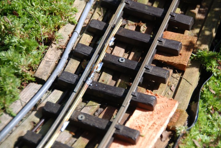
| Check Rails
Research shows that Inner 'check rails' have in addition to being fitted at points and crossovers have been fitted to normal track where curves were tight as they helped prevent derailments. They were first used as far back as 1729 on a horse operated wagonway in County Durham and they were used on the steam hauled railways wherever the curves were less than about six hundred foot (183m) radius. That is equivalent to about a 5.7m radius (5700mm), which gives some idea of how very tight a "G" scale model railway curve is at 600mm radius. May be check rails are still seen today on tight curves, with the check rails only being laid adjacent to the inner rail on the curve. Check rail on the DRL as at April 2009 |
|||||||||||||
| Some
experiments
I have now down some very basic time measurements of a truck taking the "dangerous" 600mm radius bend. If you looked up the page you will note some calculations which I have found them to be most accurate at predicting the speed 3.46 mph at which a roll over force applied causes derailment. The timing results were as follows:-
So even the slowest just rolling speed is in effect far to fast for the speed to be life like .... Further experimentation When I know the following:- 1. at what speed do narrow gauge locos run at maximum 2. approximately what is the weight of a single narrow gauge coach 3. many many coaches make up a narrow gauge train.
|
|||||||||||||
|
|
|||||||||||||