|
|||||||||||||
Scratch Construction ------- Electronics used on the Railway |
|||||||||||||
In the early days of the DLR I used reed switches and magnets attached to the loco or carriage or truck so that as it passed over the reed switch it closed the circuit and performed a function. Sometimes this was to change lights and some times to indicate the position of a train in the tunnel. This all worked well for about 6 months and then with more visiting locos there were insufficient magnets to go round and also in some cases difficulty in fixing the magnet to the item. Thus in December 2008 I decided to go down the route of IR (infrared) detection. I came across the site
|
|||||||||||||
|
|||||||||||||
| When I purchased my first IR transmitter
and IR receiver I had no idea which pin of the LED look alike did what.
As you can see in the diagram the LED Tx (transmitter) and the phototransistor Rx (receiver) look similar even down to one leg of the connector being shorted than the other. The LED Tx does work just like a normal LED in that the Cathode is connected to the Gnd ( O Volt line and the Anode to the + Volt line but via a limit resistor to stop it blowing up !!! The Phototransistor, a transistor without a base leg with the shorter of the legs as the "Collector" and the longer leg as the "Emitter". The Emitter is then connected to Gnd and the Collector to a resistor to determine the gain of the circuit. The Output is then fed off to another part of circuitry to control the system you have developed.
|
|
||||||||||||
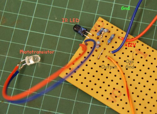
| I made up a simple test board to
check the operation and it was only then that I did discovered that if you
connect the wrong leg of the phototransistor to the wrong place that it does
not blow up but just not work.
The photo show my first test board. Being a test board I have to add components to obtain the results I wanted hence the two resistors linked out of the board. The Red wire went to +12V and the Blue to Gnd and the Orange / Red went to the Output. The other wire sticking up was for the Gnd connection for the oscilloscope I used to test out the circuit. With a supply voltage of 12V The resistor values were R1 = 470 Ohms and R2 = 44k ohms |
How can one check the IR LED is working. Use a video camera and look at the LED? Such camera can often see IR light and if so it will show you all is well. |
||||||||||||
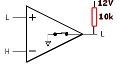
| With the system I wish to develop
I am to use a reflection of the IR LED to the phototransistor and not one
that breaks the path.
With this the output from the IR system goes from High to low. This Low is then fed into the + of the Voltage Comparator gives a Gnd output. The output from the comparator operators like a switch and pulls the output the GND. To make it show a difference an external resistor needs to be used to pull it high when not in the Grounded state. |
|||||||||||||
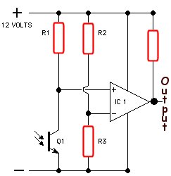
| Q1 is the photo transistor with R1
its bias, R2 and R2 provide a potential divider at approximately 50% voltage
so about 6 V.
In this configuration with IR light falling on the phototransistor the Input to the comparator will be low and the output held high by the resistor on the output. In this configuration with no IR light falling on the phototransistor the Input to the comparator will be high the output will go low. For the rest of the signal gates circuit it does require the out put pulled to Gnd which will operate the start of the level crossing gates. By reversing the + and - input the reverse would occur. |
|
||||||||||||
| By Experiment carried out
in late december 2008 it was found that the reflected IR beam whilst detected
at night suffered greatly from IR from the sun during daylight hours. A decision
was made to us a IR beam and to point the IR detector downwards and thus
lessen the effect of the daylight. This has improved the situation but not
fully overcome the problem so little shades were made for the detectors.
More development continues. |
|||||||||||||