The Diary of the Building of a 5" gauge Stirling Single
|
|
|
|
|
|
|
Cylinders and pistons Part 2 |
|
| 22nd June 2010
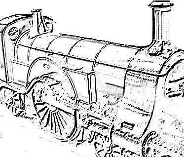
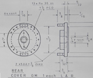
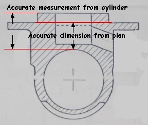
I decided to tackle the cylinder covers next. An extract from the plan shows the fitting for the cross head slide and that is as it is on the actual Stirling Single at the National Railway Museum. Setting the rear cover of the right hand cylinder in the lathe careful cuts were taken to remove the flashing from the casting and then everything was brought to size, the hole drilled and reamed and all is ready to tackle the front of the rear cover. |
|
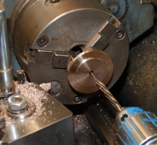
| 23rd June 2010
I completed the machining of the rear of the rear covers. Being GM they are prone to move in the chuck if too deep a cut it taken so 0.1mm cuts were taken to ensure no movement. The bore was then made with a slightly smaller drill than the 1/4" reamer and then the hole was reamed. |
|
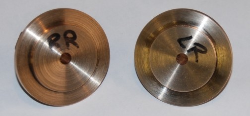
| Here are both complete on the rear.
They are a fraction different in bore registration so are not
interchangeable.
They will be stamped in due course so that they are marked permanently. |
|
| Today also saw the completion of the front covers. | Picture to follow |
|
|
|
| So what comes
next.
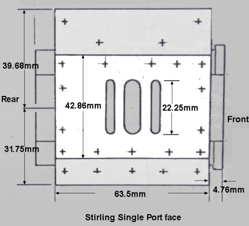
Next I will be moving over to the milling machine and setting up to mill ports I will need to mark them out on the port face & use a slot drill in the milling machine to machine the ports. I will really have to think about this part of the process, as I am sure it is easy to foul up & spoil the work at this stage. I have been advised to hold the cylinder between two angle plates with a long bolt or studding through the bore with the port face upwards as the front ends have been faced off as well. The cylinder level by mounting a clock gauge touching the port face and moving the table about or laying a steel rule across the port face and checking the height either side off the table with a height gauge. Once this is achieved the machining can be considered.
The depth of the step from the port face to the bolting face is found by:-
So set the milling cutter to just brush the port face and then lower the mill the depth of the step and lock the head before milling both bolting faces. You can get an exact depth of cut by putting a dial indicator mounted on the table and the pointer on the milling chuck or of course use a DRO if you have one on your machine. While it is in this setup you could also mill the ports. After the ports I will need to drill the steam ways which like the ends of the cylinders with the two outer ports. First I will need set up the cylinder mounted at the correct angle in my milling vice and mill a flat on the inside edge of the cylinder on the steam port side. Next the flat will be centre popped for the hole locations. In the next stage remember to CLEAR the Swarf REGULARLY, as a drill breaking at this stage would not be a good thing either. Then carefully drill the steam ways making certain that the drill doesn't burst through the port side and continue into the other side and thence into the next port. After all that I will machine the front and rear covers & drilled the holes in them for the cylinder cover bolts. And in the next stage remember to CLEAR the Swarf REGULARLY, as a drill or tap breaking at this stage would not be a good thing. Then drill & tap the holes in the cylinders. I will use the covers as a drilling jigs to ensure correct alignment of the holes. |
|
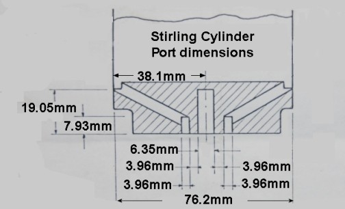
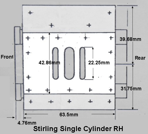
| 21st June 2010
I decided to purchase the remaining DRO for the milling machine and a large read out. All being well it should arrive this week 3rd week of June 2010. I have also been looking in detail at the drawings to work out the dimensions that need to be cut when the milling starts. Opposite is a drawing which shows the port dimensions in metric. |
|
| But this is just as important as
the port face must be the right size to go through the hole in the frames
and have sufficient fixing area to the frames.
I shall check dimensions against the frames in due course.
MOST IMPORTANT The drawing is showing the left hand cylinder. |
|
| This is the right hand cylinder so they will be marked on the port face as to which is to be which !!! |
|
| Marking out ready to cut | With a full set of DRO (Digital Read
OUT) there is no need to actually mark out for the cut EXCEPT to make sure
you know what measurement to cut.
The only mark that is preferable is a centre line of the bore which is difficult to access and mark but with time it can be achieved one way or another. Sorry I can give no more explanation. |
| Notes on the Pistons and Piston Rings | The actual pistons must NOT be a
tight fit in the bore of the cylinder in fact they must NOT touch the cylinder
bore.
The part that will be a tight fit is the piston ring. This is made from drawn phosphor bronze machined to a size a little over the diameter of the bore plus the thickness of a junior hack saw and about 1/32" (0.79mm) thick and then parted off the thickness to the slot in the cylinder. A cut is then made through the ring with the junior hack saw and the ring tried for size in the bore. IT SHOULD NOT FIT !!! Use a double sided flat needle file to file both side together si that it does not matter if the file is at an angle the slot will still close up equally. Test the fit in the bore and at the moment that the ring just slides in is the moment to stop and fit the ring to the piston. |
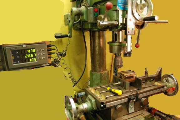
| 3rd July 2010
Installed the Digital Readout on the milling machine. It took all day to sort it out and I still had to make up a stronger bracket for the vertical "Z" axis on the 7th July2010. |
|
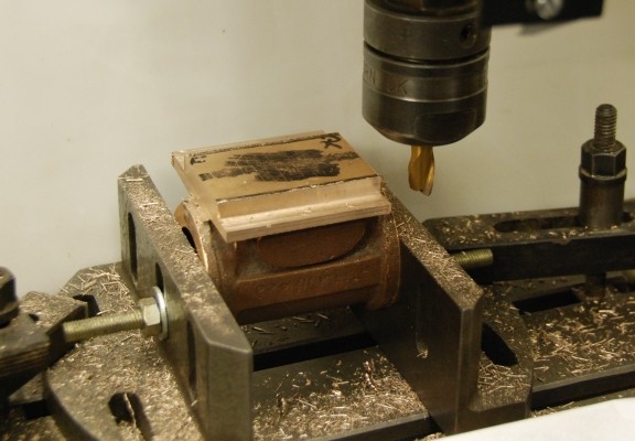
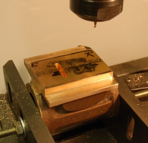
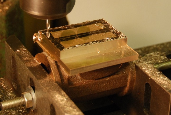
| 7th July 2010
The milling of the cylinders started with the four sides of the face being milled to size. Do check that the locking bolts that hole the parts are secure as are those that hold the head of the mill and disaster can normally be averted. I thought I had done that but I had omitted as in the picture above to clamp down the left hand end and to fully tighten the bolts holding the head of the mill. When all tightened and taking fine cuts all went well. |
|
| The DRO was a joy to use and the
guide marking out proved to also be an asset as I knew that I was cutting
to the correct dimension.
I still had to check dimension with the usual digital caliper as the cutter, a 10mm slot mill, and the DRO did not given finite dimension so either the cutter was a 10mm was in fact fractionally of the DRO is just slightly out - I am taking about 0.09mm so not much at all !!! |
|
| 8th July 2010
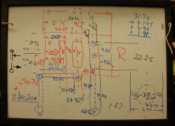
Well the milling of the first port was completed. The DRo proved worth every £ that it cost !!! |
|
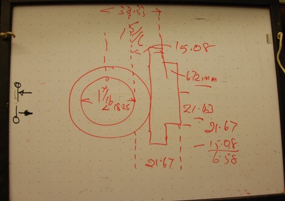
| To try to avoid errors I used a white board again to work out the DRO readings (in Blue) from the actual plan dimensions (in Red). |
|
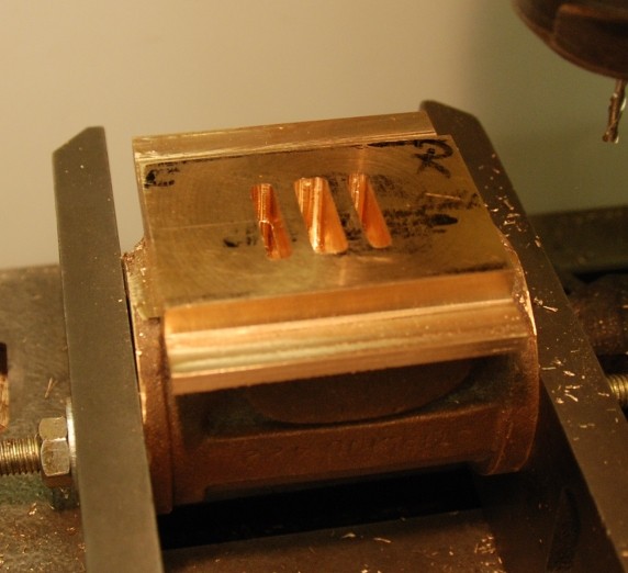
| 9th July 2010
The milling of all three ports now completed and to a depth of 15mm. This was made possible by the use of a 3mm long reach slot drill. |
|
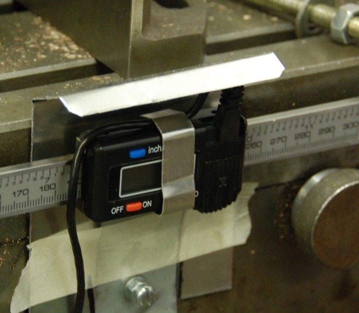
| 11th July 2010
First item to be made was using a piece of 1mm aluminium to make a simple cover for part of the DRO which would become covered in milling particles. Rather than make this cover fixed I have for the moment used masking tape to hold in position. When it is proved successful that I will bolt it to the unit. |
|
| Easier second time round.
The setting up took an hour including the calculations for cutting and the milling took an hour. The original 10mm cutter has been removed and the 3mm cutter out in place and the X and Y axis set to zero position so that the DRO could be turned off. |
|
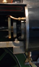
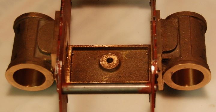
| By 15:30 today both cylinders are
completed except for cross drilling into the ports which can wait for another
day !!!!
Note they are only in a temporary position as the spreader at the bottom needs to be fixed with counter sunk bolts hence the reason why the cylinder on the right of the picture appears to be out of alignment !! |
|