The Diary of the Building of a 5" gauge Stirling Single
|
|
|
|
|
|
|
Cylinders and pistons Part 1 |
|
| From discussion with Martin
of the MMES, June 2010, I have decided that this is the method I will be
using to produce machined cylinders.
These are the items I must consider before machining the cylinders:-
Then the cutting operation will be:-
|
|
| 6th June 2010
Before I made the first cuts I put up a white board so that I could convert the drawings to metric and confirm that I knew what I was trying to achieve. The the first cuts were made on the cylinders to create a datum line from which all else will follow. the cylinder was clamped to the face plate with a packing piece with slight "V" in it was placed behind the cylinder. |
|
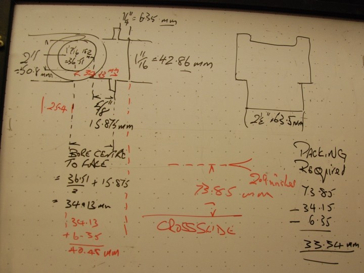
7th June 2010 This is the white board with the scribbled notations to help me understand the drawings.
|
|
| The lathe set up to take
the cuts to make a datum.
I had scribed a line to indicate the least amount of material to take off to lead 1/4" as shown on the drawings, an the aligned the line at right angles to the lathe. The casting was securely attached to the face plate and held in place by two large bolts and a 1" x 3/8" steel bar. The cutting was carried out by a tipped tool I have,
|
|
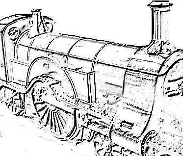
The first casting before machining and not a hint or any bubble holes that would be found during the machining .
|
|
The first casting after the initial machining. Note the air bubble pitting. I contacted the supplier but as it was under previous ownership and the casting were bought in about 1990 it may be that I will have to buy a new set !!! Still it is the first set of casting to go wrong !!!!
Before I buy a new set I will continue with the machining and have them looked at by the "experts" in the local engineering club ....
|
|
8th June I was able to establish, and double check, that the spacer I need to place below the Stirling single cylinder valve face is 33.87mm and not the original 33.43mm as in the drawing above. I cut off a piece of 3" BMS and machined it carefully to that exact measurement in readiness for the boring operation. |
Picture to follow |
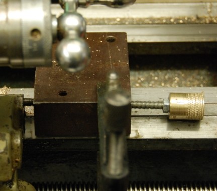
| In due course a boring
bar will be required so here are some first thoughts of a between centres
boring bar.
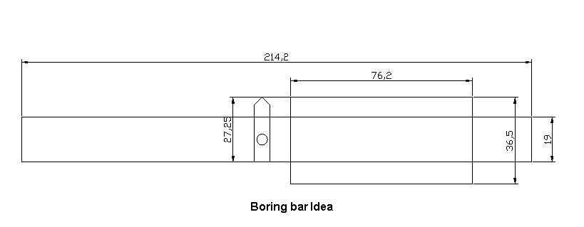
I have not drawn in the centres or the facility to driving the bar but this will be needed and to engage with a dog clutch part. It may be necessary to have two cutting tools one to start the cutting and the second to make the finish cuts.
I am further told that whilst it is good to have lathe centres which are in line however for this application it is totally irrelevant because even if the boring bar was at a slight angle to the bed of the lathe, the tip of the tool will still rotate in a circle and as one is are passing the cylinder across that fixed circle you will still get a perfectly parallel bore. This is the great advantage of boring between centres. Although it is called "between centres" one can hold one end of the bar in a 3 jaw chuck with a revolving centre in the tailstock. Again, it does not matter if the chuck does not hold the bar truly in the centre.
|
|
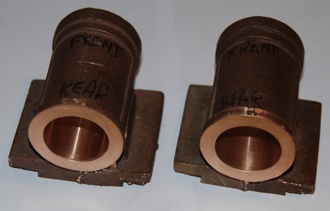
| 13th June
Chatting with a friend at MMES I learned that some dimensions are not critical but that others are and they are not the ones I expected. Firstly the bore of the cylinders MUST enter and leave at the centre of the casting POINT A else the covers will not sit correctly on the ends of the cylinders. Secondly When you machine the step for bolting to the frames, the dimension from that face to the bore centre , dimension D is critical as that gives the distance off the frames of crossheads, slidebars, motion brackets and con rod so be careful with this one!! With this type of cylinder, you cannot move the bore, it is dictated by the shape of the casting and there is no latitude for errors here. Thirdly whilst is will be nice to have dimension C correct there is a little latitude as the internal valve gear is associated with the eccentrics and positions are slightly movable. Lastly when you bore the cylinder, you must face the end of the casting without moving it and that end MUST be the back end of the cylinder so allowing the piston to run true, the front does not matter if it is not exactly square to the bore. At this point the castings are handed so mark which is which.
To ensure accuracy it is suggested that both ends of the cylinder are fitted with wooden bungs to make the alignment easier to achieve.
|
|
15th June I went to Axminster Tool Suppliers and purchased
This is all in preparation for the machining of the cylinders and drilling the main wheel cranks. |
|
| 18th June 2010
Practice fly cutting went ok, well not too badly all things considered but I found that when using the saddle I had no way to moving the saddle just a fractions of a mm! So I devised the micro attachment in the pictures opposite. The big steel block had luckily for me been milled with a 90 degree cut so that it sat well over the bed of the lathe. I drilled as deep as I could with a 4.2mm drill, the tapping drill for M5 x 0.8mm and then had to counter bore the other end 9mm so that the threaded bar could poke through once the M5 tap had been run into the tapping drill hole. Then I made up the brass knurled knob and put 4 graduations on it and with the pitch 0.8mm this meant that each would advance the saddle 0.2mm then half a division 0.1mm and half that 0.05mm is about 2/1000th ". The big chunk of metal was then held in place with the machine clamp. After adjustment the saddle was locked before a cut was made. This was then tested but using a normal cutting tool in the lathe onto a brass chunk of metal. Total time to devise and make 3 hours.
|
|
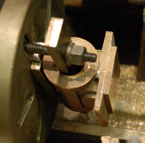
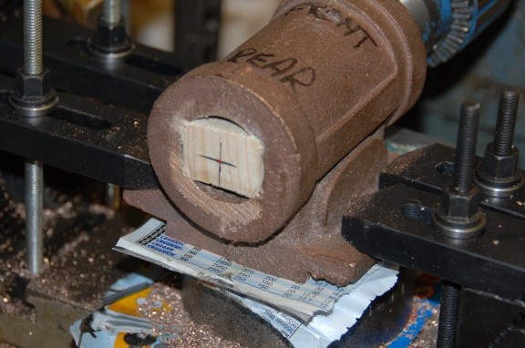
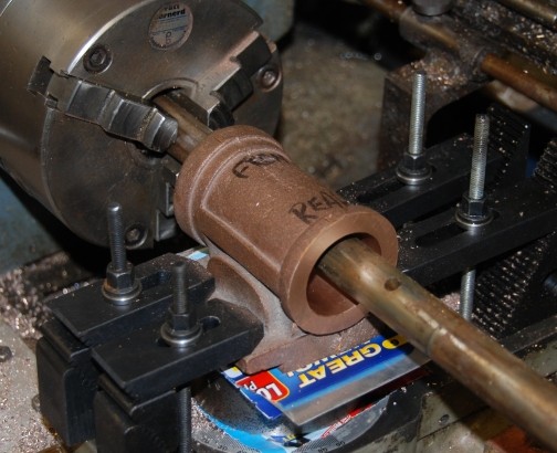
| Still the 18th !!
Here is the set up for boring the cylinder. The cylinder is firmly clamped down with thin paper between each metal surface to aid stopping any slipping of the parts on a metal to metal surface. I hope you can just make out the laser lining up dot in the centre to the block of wood. I did the same at the rear with the laser held in the chuck in the tailstock.
|
|
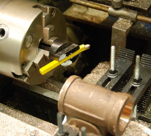
The boring bar I made in 1992 and I just had to make up two additional tools to go in the bar to achieve the correct depth of cut.
|
|
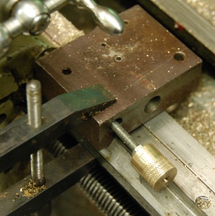
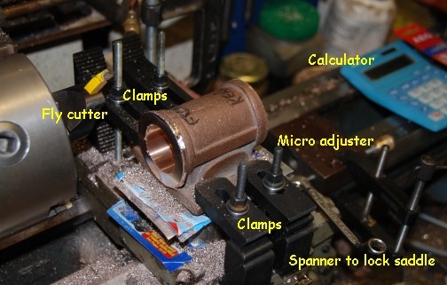
| This is the set up for fly cutting with additional the micro advance as shown above. |
|
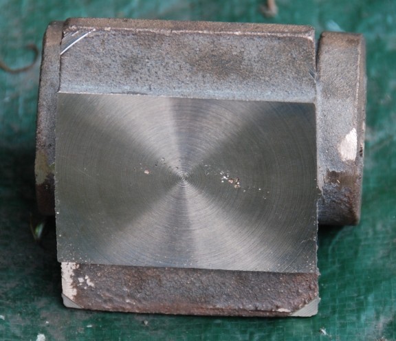
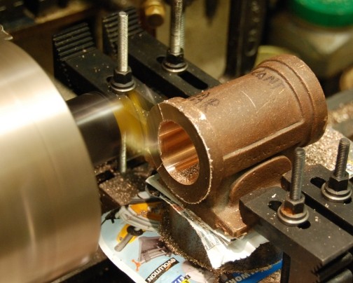
| Fly cutting in action. The depth of each cut was 0.6mm with finished cut of 0.1mm. |
|
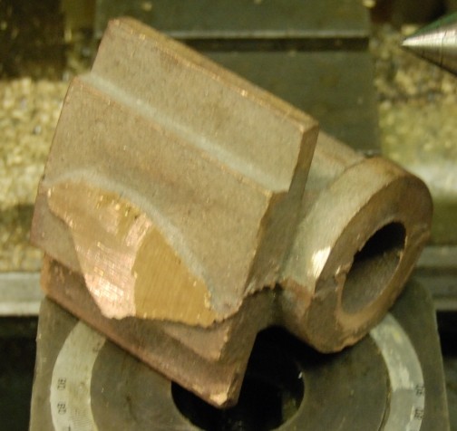
| The first cylinder bored and the
rear end faced.
Total time take about 3 hours ... no need to rush !!! |
|
| 19th June 2010
Second Cylinder bored and faced at the rear end . |
|
| 20th June 2010
The initial setting up was carried out using a bar which ran true and the bore brought up to touch the side of the bar. The accuracy was then checked with the laser pointer as shown below.
|
|
| Note the red dot on the end of the cylinder. This is a laser point aligned with the bore edge. |
|
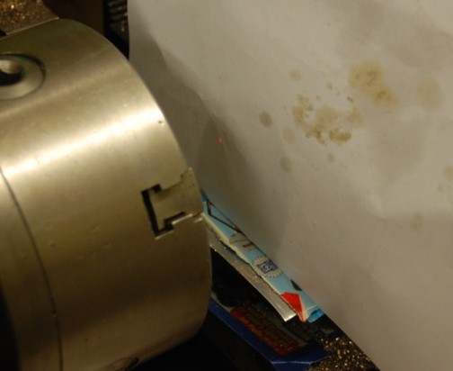
| Note the red dot on the sheet of paper. This has just appeared as the dot the other end went over the edge of the machining showing that the bore is as near as needs to be for the front end. |
|
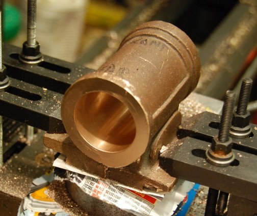
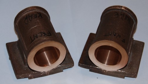
| The cylinders are now both bored and faced at each end ... |
|
| I thought now that all is completed
I would identify all the parts needed to fly cut the ends of the cylinder.
Note the paper sheets between each metal surface to ensure that slippage does not occur which is possible on the metal to metal surface. I must say that with out the micro adjuster I could not have achieved the accuracy that has been achieved. |
|
|
|