The Diary of the Building of a 5" gauge Stirling Single |
|
|
|
|
|
|
|
Completion
of the build Part 3
|
|
| 21st
April 2019 As it is Easter Sunday the afternoon will be spent with family and as I have a painful right knee I am not doing anything significant in the workshop. However I have located the paints I have used before on the engine wheels and the same paint can be used on the 3D printed parts. I have also taken a look at the plans to try to understand what needs to be amended to make the regulator operate. |
|
|
22nd
April 2019
A
trip out with the loco to my club MMES located in Mote Park
Maidstone.
Amongst
the recommendation were to:-
All
in all a very good morning chatting with friends.
|
 |
| 23rd
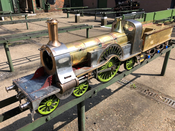
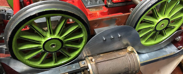
April 2019 Today has been spent stripping down the loco chassis, turning it upside down to work on the valve gear which seemed slack and also needing to make up a spacer to stop a longer than necessary pins striking parts it should not. |
 |
| Also
considering how to complete the make up of the splasher for the
front bogie and assessing how far it will turn to go round a
corner. The photo shows the underside of the cylinder with
a bung missing when photo was taken. I was able to machine 0.1mm off the gudgeon pin through the connecting rod and reduced the edge so that there was no sharp corner to catch on the splasher. Rear wheels of loco were also checked and oiled up. The cylinder drain cock holes were filled with their bungs. |
 |
24th April
2019
With the
recommendation of club member to check that the loco went
round tight corners I took the stripped down loco to the track
and proved that YES it would go round the tightest bend on the
traverser without derailing. With that proved the build can
continue.
|
|
|
25th April 2019 Today started with watching some Keith Appleton YouTube on his Stirling Single and very interesting it was to to see he uses a rolling road similar to the one I have. This made me think that I too wished to see the wheels of the loco go round again. First I decided to shorten the bolts taking the exhaust from the cylinders which I had not done previously but all shortened now. |
 |
| Then
I made up an air compressor link to the engine and ran it on air
for a few minutes. Currently the water pump is not on the engine as I need to make up a fitting that will go in the top, the pump exit, and not foul the boiler which the current on does then with that done I can pump some water !!. |
 |
| 26th
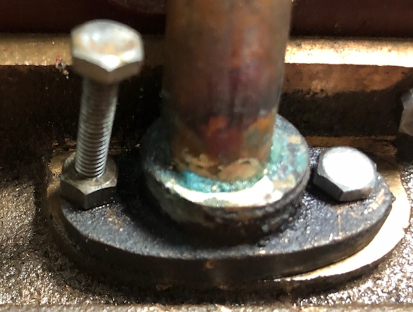
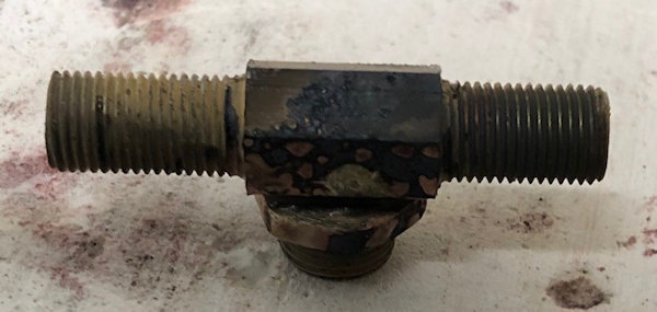
April 2019 With the success of making the wheels turn on air today attention was turned to making the Axle Pump function. There is so little space under the boiler when in place that major alteration had to be made such as reducing the 1/2" ( 12.7mm) up stand to only 8mmn and then recessing the ball seat inside the top part to allow for this reduction. After amending the pump attention was turned to making making the tee piece which checked out well attention was turned to the pump. The original top seat was used and it was machined down to a small spigot to enter the recess I made in the threaded hex bar. |
 |
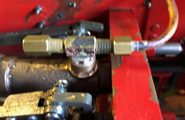
| With
everything made and fitted including some temporary pipe work
and a tray of water under driving wheels compressed air was
applied and I am pleased to say the pump pumped water and at a
good pressure. The only problem now to solve is the leaking from the back end of the pump where the plunger enters but that is for another day !! |
 |
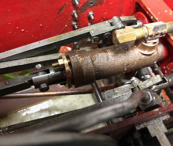
| 27th
April 2019 Chatting to a club member Tom it was suggested hat I take about a meter of PTFE tape fold it in half and in half again and then twist and use that as the packing for the rear gland of the water pump. I left the old packing in place and added the new PTFE packing and ran the chassis on air. I am pleased to report no leak !! Whilst one could say not much done today but a great result. |
 |
| 28th
April 2019 A friend called Dave has given me a drawing of an oil check valve which I am trying to use with my lubricator which does not stop steam working back into the lubricator body. It is a difficult problem due to space restrictions. However I had an alternative lubricator and which has bottom exit so with a bit of modification to the original bracket I have moved the lubricator to the rear an amount of the original fixing holes ( about 25mm) and supported it on brass angle which was filed away to give room for the union on the bottom which now does not interfere with the bogie axle below and as necessary packed out by 4BA brass nuts. Two blanking pieces were made up which will be used as unions when I have the correct pipework and nipples. This lubricator does pump oil !!! |
 |
|
29th
April 2019
This
morning a list for pipe work was made and then off to
Staplehurst, out of necessity, to purchase and then proceed
with use of the purchases to link up the new lubricator.
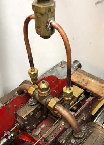
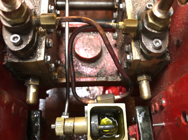
The
pipework comes from the underside of the lubricator, as on the
left of the photo and then to a tee piece and the exits via
the two unions which attach to the steam inlet on the steam
chests.
|
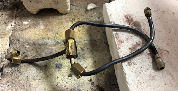 |
| The
bending of the pipes required two annealing sessions so that
they were easy to bend into position and now they will work
harden over time . You can see how little spare space there is
!! Very pleasing to have the lubricator working and thus another good step towards running on steam. There was no trace of blow back of air which was the case with the original lubricator. |
 |
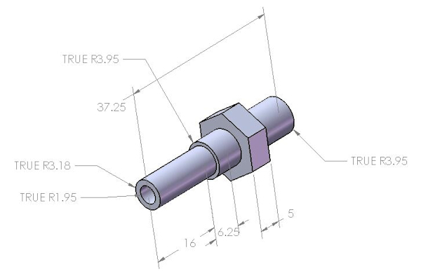
| 30th April 2019 After watching one of Keith Appleton's YouTube videos https://www.youtube.com/watch?v=b1EwkdmI6bU I made up this drawings but sorry I could not work out how to do the threaded parts. As my lathe is Metric the dimensions are in mm for my convenience. Do check the dimensions to make sure they meet your requirements if you make them !! The end needs to be rounded to allow tube to be pushed on. |
 |
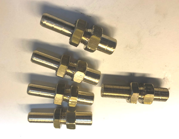
| Here are the parts
made ready for use when the pipe work is in position. I hope
they do justice to Keith Appleton's idea. The fully threaded connection is for the water under pressure from the tender hand pump. |
 |
Link to next page |
|
