The Diary of the Building of a 5" gauge Stirling Single |
|
|
|
|
|
|
|
Completion
of the build Part 2
|
|
| 6th
June 2018 Some pictures of a little bit of progress. |
|
 |
 |
|
14th
April 2019
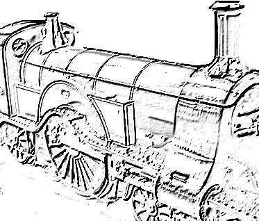
The
loco back on my workbench showing more of what has been
carried out.
I
have ordered a new set of plans from Reeves so that there is
no delay in me starting work.
|
 |
| Inside
the smoke box is very tight as the photo shows and again I need
to learn what is happening in there ... |
 |
| The
splashers on the wheels look great but I will need
remove the rust prior to painting. This rust removal will be done in my Sand Blaster. |
 |
|
15th
April 2019
With the loco on the bench I took a look to see what's what a list out things that were obvious to do. for the loco 1. the regulator does not operate 2. Sight glass fitting need aligning and glass fitted 3. Make the boiler door catch and fit 4. Sort out the coupling to tender 5. Fix chimney to smoke box 6. Amend the fixing of the cover plate above oiler 7. Sort out axle pump as will not fit under the boiler. 8.
Provide the blower outlet in the smoke box
9.
Seal up the bottom of the smoke box so that a vacuum can form
to draw the fire
10.
Fit lugs on the side of the boiler where it will sit on the
frames adjacent to the firebox.
Tender
1.
End caps for the axle boxes
2.
Coupling to main engine
3.
Sort out the pipe work to connect Tender to the main engine.
|
 |
|
The
smoke is removed to show the oiler and the two inlet pipes
which when coupled to the boiler to allow steam in to the
steam chests.
With
the smoke box removed I can sand blast it fit the chimney and
then spray paint with high temperature paint.
The
axle pump has now been removed to start the amendment so that
it will fit under the boiler.
I
am considering cutting down the top of the pump and making a
right angle fitting to more economically use the space
available.
|
 |
| The
water filter was just a little tight in the fitting so a very
fine skim was taken to make a satisfactory loose fit. |
 16 16 |
|
16th
April 2019
Not feeling up to doing any critical work on the loco so working on the plans and what tooling I need to make the little handle for the reverser. The
lever part is about 1" so a great deal of fine filing and
milling to do let alone drilling some very small holes !
I
shall for the rest of the day work out if I have materials and
milling cutter to achieve this item and also what size spring
is required !
|
 |
| Having
a 3D printer I decided to draw up the 3D STL file of the
Axle Box covers with oil ways. The 6 covers will take about 2 hours to print and the they will need to be painted and fitted. |
 |
| 17th
April 2019 Over night I 3D printed the axle box covers and they are now ready to attach to the axle boxes. As they are to be painted I used PLA filament and the print time was about 2 hours on my Creality Ender 3 3D printer. The fitting have an oil way so I can oil the axle bearings. |
 |
| 18th
April 2019 The axle box end covers were super glued into place and are now ready to be painted. |
 |
|
When
I made the Tender chassis I did not have the loco chassis
completed so I did not know the dimension which on the drawing
said "Check from the Drag Beam of the Loco."
So I checked the dimension and marked it out, drilled three 6 mm holes and the use a small file to join the holes and the a bigger file to finish to size as shown in the lower photo. There
was not enough time today to make up the pair of brackets as
seen in the drawing lower down.
|
  |
| 19th
April 2019 So today is the making and fitting of the drag beam drawbar angles. Two pieces of angle were cut from stock, reduced in size, and the drilled for the fixing rivet holes and coupling. |
 |
| The 1/8" rivets were
then cut to length and outer holes counter sunk and the parts
joined by the rivets. |
 |
| Finally a drill was put through to slightly widen the coupling hole and the unit refitted to the Tender Chassis. |  |
| 20th
April 2019 The lamp bracket on the cover for the cylinder oiler was made captive to the chassis by the bolts holding the lamp bracket. With the lamp bracket bolts removed the plate could be removed so I decided to rivet the lamp bracket into place. |
 |
| I needed to recess the
holes so the the rivets did not make the plate covering the
oiler proud for the remaining parts. |
 |
| To drill the coupling
holes in the loco drag beam I had to devise a long drill by
drilling out a piece of bar by the drill to drill the hole and
then using engineering adhesive 603 secure the drill into the
bar. The resaon for this is the with the regulator inplace when the loco was returned to me it would need to be removed to drill the hole. The drilling was a slow process may be my drill was not sharp but in about 15 minutes the two holes were drilled according to the plan dimensions. |
 |
| Next the coupling pin was made up and fits loosely in the hole, but will be fitted with an "R" clip when in service. |  |
| The coupling bar was made up and drilled to size and with a coupling pin also made for the tender the engine and tender were coupled for the first time EVER !!! |  |
| From the time I
started the Tender I have made a mistake and just bolted the
dummy springs into place. They should have been held by 6BA bolt
from the back and not right through. So today I drill our the dummy springs and tapped then 2BA expanded the size of the hole in the tender chassis and refitted the springs. |
 |
| The refitting takes
away the nasty bolt hex heads. The plan now will be to shorten the bolts and may be use some filler so that when painted one might not even know of the error originally. |
 |
| Continue to next page 24b | |