The Diary of the Building of a 5" gauge Stirling Single |
|
|
|
|
|
|
|
Smokebox |
|
| There is a great deal that goes on in the smokebox. | |
| 26th July
2009
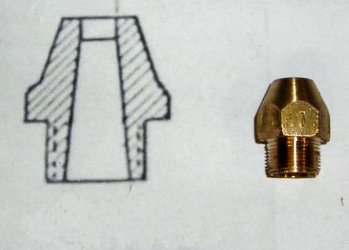
Wanted to do something different so set to work to make the first part associated with the smokebox. The Blast Nozzle is an important part so needs to be made carefully !!! |
|
|
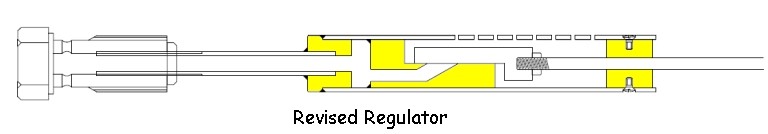
27th June 2010 The drawing is an extract from the plans to help explain how the regulator parts come together. |
|
|
28th June 2010 However as I wish to use a banjo idea at the front end it can be done further back in the boiler The drawing shows how it would work. So just because a boiler does not have a dome, it does not mean you have to put the regulator in the smokebox which is very tight for space in the Stirling smokebox. |
|
| With the
regulator as it is drawn, the threads do not have to be the same
pitch because the regulator can be fitted to the banjo bolt and
lock nutted before the bolt is screwed into the boiler as no
other part of the regulator attaches to the boiler. The only
check that is needed is that the regulator inlet holes are at
the top when the bolt is tight. In
fact this arrangement was not used. |
|
|
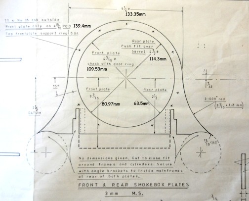
9th August 2010 Today has been spent understanding the drawings and drawing up .dwg laser cutting patterns for the Front and rear smokebox plates and the sheet that will need to be rolled and then cut to size to make the barrel of the smokebox. |
|
| 10th August 2010
The Campbell laser cutters of Chatham have done a great job and so quickly on the smokebox plates that I can now proceed with the rings machining. I have also had a piece of 2mm steel cut to be formed into the ring between the two plates. |
|
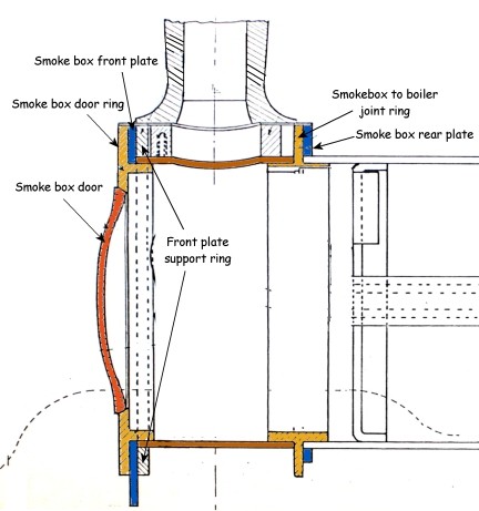
| The smokebox is a rather complex affairs so I have done a drawing and coloured in the various part in an effort to help understanding. |
|
| 11th August 2010
Sorting out the drawing above was certainly not a waste of time as when it came to machining up the :-
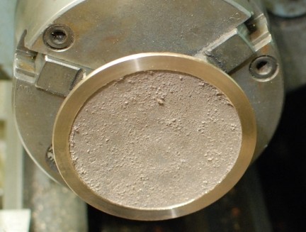
it all proceeded very well. First up was the smokebox door here it held by a spigot at the rear. The door is faced to size and diameter. Then a 15 degree chamfer was put on the edge so that is sits into the smokebox ring as per the drawing. |
|
| Then came the smokebox ring.
The pictures show the front face of the ring and the 15 degree
chamfer has been applied by the cross slide being turned through
the 15 degrees as was done for the door.
|
|
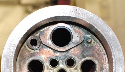
| Then it was the turn on the
smokebox to boiler ring. This has to be turned to a good fit
inside the boiler barrel and the out side ring turned to be a
good fit to the rear smokebox plate and the same on the reverse
side.
|
|
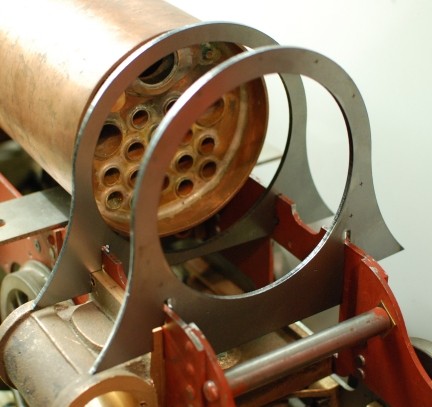
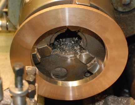
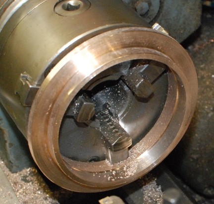
| Also the inside had to be
bored out so that it misses the internal parts of the boiler.
As can be seen there is not much room and the thickness of the ring was reduced to 2.5mm and this clears the parts as checked with a 3mm rod. |
|
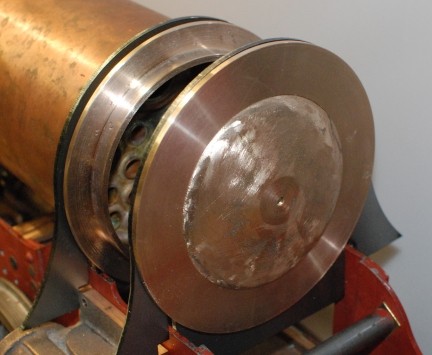
| So this picture shows where we have reached at the end of the day which earlier had seen me at my model engineering club rolling the tube that will fit between the two parts where the gap currently exists. |
|
| 15th November 2017 I chatted with a friend about pipe bending for the exhaust and he suggested filling the pipe with a fine grained sand and stopping up the ends with hot melt glue and bending around a timber former. So draw up a former with the inside profile of the pipe and cut that into a piece of wood and make two cheeks one each side of the of the former. Then make a stop to hold the pipe in a fixed position so that I can bend the free end. The drawing is as done in the "Pub" on a "napkin", so rather up market from the back of a "fag Packet" ! |
 |
| 17th November 2017 From the description above the photo shows the form that the pipe bending will take. You can see he paper template which was drawn onto the wood and then cut-out on the band saw and smoothed on the linisher. The cut out and a side piece were then glued to the back piece and allowed to dry over night. You can see the pipe set as a spacer and that will be the stating side with the pipe bent over from left to right. If there is any spring in the pipe after bending adjustments would be made by careful hand bending. |
 |
| 18th November 2017 I was able to purchase some play pit soft sand but it was rather wet. So I dried it in my glass fusing kiln by allowing it to heat up to 300C. The pipe end was then sealed with hot melt glue and the sand poured in and then the open end also sealed. |
 |
| 19th November 2017 The pipe is bend to shape and cut away from the extra. However I am not satisfied with the second bend so will remake that part and prepare to assemble. One end has to be flared open and a collar made and put on before silver soldering the other end into the exhaust port fitting. |
 |