| There are many small pasts
to be made so this section is devoted to them |
| 6th October 2010
The main bearings
The main bearings were a simple turning
job but to be able to cut the ends to the right length meant that I had to
fabricate a holding piece which gripped the outside but allowed the end to
protrude further than the depth of the chuck.
Sadly one piece did not grip well and
resulted in slight score marks but being on the out side and with set into
Aluminium I cannot see that as a problem - at the moment. |
 |
| Two spacers to the flywheel and timing
cog. Again simple turning exercise. |
 |
| The Main bearing caps are an aluminium
casting and need to be generally cleaned up to remove the casting flashes
and then one of the bearing caps was drill at centres of 45mm and 5mm the
drill size to tap M6. The drilled holes will eventually be used as the location
for the drilled holes in the lover casting where studs are to be
installed.
The the first bearing cap was used to
locate the holes in the second bearing cap and 2BA bolts used to holed the
items together for boring to size 26mm diameter.
The photo shows the set up ready to be
bored.
The boring is straight forward and very
quick !!!! |
 |
| 7th October 2010
The
big end bearing
Well of course it is no good cutting
the bearing AFTER machining else the two part do not meet and would tend
to crush the shaft running in it ... So a suitable length was cut from the
35mm bar of PH BRONZE with a new blade in the band saw which was then cut
it in half length ways. It needed support it in the saw by means of two pieces
of metal one each side, as holding by hand for a 30 minute cut was out of
the question and would not have been as straight a cut.
Then was then mounted it in a 4 jaw chuck,
checked with a DTI to make certain it was in the centre NS ( up down ) and
EW ( side to side ) so to speak and then proceeded to machine it.
In the photo note the two pieces of thin
packing to ensure that the jaws landing on the cut do not allow the work
piece to move.
All that remains now is for the work
piece to be put into the purpose made split jaws similar those in the top
photo on this page and for the other end to be machined to finished
size.
|
 |
| This is the completed Big End Bearing
, shown against a one pound coin. The two parts will now await the completion
of the con rod which is a very big task. |
 |
| 8th October 2010
Cam shaft
A generally simple turning and threading
M6 x 1 project. |
 |
| Gudgeon Pin
Also a simple turing task but care needed
to ensuring correct length |
 |
| 9th October 2010
Head Gasket
I ordered gasket material from
gaskets
direct limited on 8th October and the material arrived to day fantastic
service. |
 |
| Governor
The photos shows some of the parts made
for the governor.
The two parts top and bottom have to
be silver soldered into another part which is yet to be made, then drilled
and the two wings the centre two parts attached after they have had 3/8"
ball bearings silver soldered to them. |
 |
| 12th October 2010
Cylinder head studs
The five cylinder head studs were made
from 6mm bar reduced a little to take the tread. |
 |
| Cylinder studs
(for upper main casting fixing
to lower castings)
There are six cylinder studs which were
made from 6mm bar reduced a little to take the thread.
Main bearing cap studs
There are four main bearing cap studs
which were made from 6mm bar reduced a little to take the tread. |
 |
| Big end bearing studs
Only two required so I have also made
two spares !!! |
 |
| Cam roller
The cam roller is 13mm across its
face... |
 |
| Timing gear spacer
The timing gear spacer is a simple turning
job.
19th October 2010
A return to the timing gear spacer as
my timing gear is actually thicker than the crank gear the spacer has been
relieved to enable the gear to fully mesh at any part of the gear
alignment.
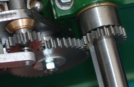
NOTE: The gears in the picture are all
the same thickness but my major gear is twice as thick as the others !!!
|
 |
| 19th October 2010
Crank gear.
Whilst the gear was cut the hole in the
centre had to be machined.
Being an irregular shape this had to
be set up in the 4 jaw chuck and centres using my laser pointer.
The white pip was painted on so that
when the gear ran at speed it was possible to check by eye that there was
no eccentricity.
As I am not yet set up for a tool to
cut the key way the gear will need to be re-set in due course !!! |
 |
| 1st November 2010
The valves was turned from Stainless
Steel using a tipped tool and plenty of coolant.
The valve was then brought to
length.
It next had to be cross drilled. The
location of the place to drill was found like this:-
The valves was set into a "V" block and
this was brought square to the mill table and fastened down.
The laser pointed was put in the chuck
of the drill and then the table was moved on is "X" axis (Left to Right)
and the X access on the DRO set to zero when the laser pointer was
seen to appear to the right of the valve stem. The table was then moved on
its X axis and the width of the stem checked to be 6mm (when the point of
the beam reappeared the other side). The table was then moved back to the
3mm position.
Similarly the laser pointed on the Y
axis was zeroed when it just appeared over the end of the stem. The table
was then moved back 3mm the hole was centre drilled and then drilled
1.5mm
|
 |
| Here are the valves and their springs
and keep washers. The springs may need to be changed when the engine is assembled
and test run. |
 |
| The rocked original casting has been
machined but a new casting will be coming to me in due course as the vendor
was not happy with its quality.
The ph bronze bearing was pushing into
the rocker.
The pivot bar was then cut to length
and the cross drilled using the same technique mentioned above for the valve
stems. |
 |
|
|