| There are many small pasts
to be made so this section is devoted to them |
| 3rd November 2010
The cam I had water jet cut but then
the profile to fit into the cam gear had to be machined. A fixing was created
by using hex bar and machining to a good fit with a large nut with integral
spacer.
Very small cuts were take of 0.3mm until
the part reached near to the diameter for a press fit into the previously
machined cam gear. |
 |
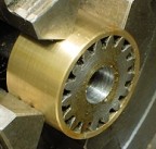
| This photo shows the finished piece
ready to press fit into the cam gear. |
 |
| The cam press fitted (with Loctite
603) into the cam gear.
The cam gear is actually twice the width
that it needs to be so changed to the supporting cam shaft will necessitate
a re-make with a stepped bronze bush to fit into both pieces.
I think this is preferable to machining
the gear thinner !!! |
 |
| The modified cam bush in ph bronze.
The bush originally designed was to support the whole of the cam and gear
so to achieve this with the wider gear the bush was machined stepped to fit
both pieces. |
 |
 |
 |
| The bush has now been positions
and secured with loctite 603. You can see that the bush is proud of the parts
by 0.5mm to allow the bush to rub but not the parts on the adjacent
elements. |
| The revised cam shaft to take the
wider component of cam and gear. |
 |
| The washer is now in place and nuts
tightened down and the cam and gear are free to rotate with just the smallest
amount of end float. |
 |
| 4th November 2010
The governor gear supplied did not have
a hole bored through the centre.
As the gear had 17 teeth it was not possible
to hold in a 4 jaw chuck and centre. I therefore turned the brass holder
bored to the same external diameter of the gear and then a single saw cut
was made to allow the brass to "spring". In fact is closed up so the gear
had to be persuaded to enter.
As it had been bored the rear of the
bore was flat to allow the gear to seat fully.
Now with the gear in the "collet" is
was possible using the 4 jaw chuck and a DTI to centre, drill and ream
10mm.
|
 |
| The governor bush was a simple turning
exercise starting at the lower end as in the picture and working towards
to taper and then lastly the part was parted off.
It sits adjacent to the gear to show
relative size. |
 |
| The governor centre was to be a simple
turning exercise but then i thought why not make it all in one piece and
save having to silver solder items in place.
The part has yet to be tapped M3 and
generally clean up to remove the machining marks and to adjust the profiles
so that it has a pair of "ears" as the part that might have been silver soldered
into place looks bottom right of the picture. |
 |
| The governor shaft was another simple
turning exercise with a 3.2mm hole drilled through the centre. |
 |
| The governor shaft with its gear
fitted by Loctite 603 as it just came out a mite too small but just right
to Loctite. |
 |
| 5th November 2010
The governor wings have to have ball
bearings silver soldered to them.
A slight depression was made in the soft
heat resistant brick and a hole drilled to be a snug fit on the piece of
1/8" bar bent at right angle and used to hole everything in place whilst
heating up and applying the silver solder.
The photo shows the "before"
soldering.
After soldering a lot of clearing up
was necessary as the surface of the ball and wing were blackened and aldo
there was a residue of flux.
A special flux was used, obtained from
the midlands Model Engineering show which came in powder form and was mixed
to a paste with the consistency of single cream.
|
 |
| Here are all the parts of the governor.
The centre "T" bar was machined from solid. It is 3mm diameter and
very gentle machining was necessary, and completed by filing of the "T"
bar.
The "T" enables the wings of the governor
to land nicely. |
 |
| 9th November 2010
The first of three oil pots has been
made. |
 |
| 10th November 2010
The small push bar support bracket was
machined from solid and a brass push bar spacer also made. These were then
fitted to the timing plate. Note there is very little clearance between the
gear and the piece. |
 |
| 12th November 2010
The brass end of the gudgeon pin were
made.
|
 |
| 13th November 2010
The key way has been cut in the gear.
To achieve this a holder for the gear was machine as was done for the other
gear.
This time the only material available
to make the holder was steel so that was used and again a single saw cut
enabled the holder to be held in the 3 jaw chuck and firmly grip the
gear.
A key way and filed up the fit the
gear. |
 |
| A spacer was made up and a small
notch filed so that it covered the keyway which was proud of the gear but
lay flat to the gear. |
 |
|
|
|
|


 TO BE CONTINUED