Problems resolved &
modifications
|
| 1. One of the biggest
problem I have resolved is stopping the main bearing revolving in the Aluminium
castings.
New oiler were made in steel and in place
of the M4 thread M5 was used and the bearing drilled out so that the oiler
thread would pass well into the bearing and just 0.5mm short of the main
crank shaft.
2. This also means that the big
eng shell could also rotate and so a pin will be installed in the outer part
and stop the shell rotation.
3. The exhaust tends to rotate
in the cylinder head when the engine is running so a nut with be made to
lock again the cylinder head and stop the rotation.
4. The main oiler delivers the
oil much too quickly so my design is at at fault and a new design will be
worked out.
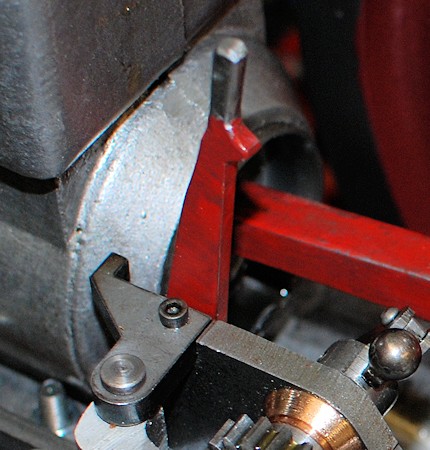
5. The lever as made originally
was not done to the plans so an alternative one has been made and this will
be tested when the engine is next run
6.
The key ways do not lock the flywheel
tightly to the shafts so the flywheel will be drilled and tapped M6 to take
a allen grub screws to lock down onto the keyways and stop rotation. |
| 6th December 2010
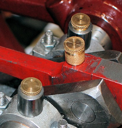
Item 1. This was in fact completed
several days ago and the new oilers look the part - in my opinion. |
 |
| Item 2. A short piece of rivet
has been put in the lower most part of the big end to stop that part of the
shell rotating which in turn will stop the upper part of the shell
rotating. |
 |
| Item 5. Made as mentioned
above |
 |
| 7th December 2010
Item 3.
The locking nuts has been
made and the thread on the caste iron fitting extended by three turns. the
exhaust has been refitted.
Item 4.
The mail oiler was taken apart and the
centre section was found that it could be reversed. Thus a 1mm hole was drill
in the centre section in place of the 3mm hole and it is hoped this will
resolve the excess of oil entering the cylinder.
Item 6. The flywheel have been
drilled and tapped and locking grub screws are now in place. |
|
| 13th December 2010
Improvement
Following a suggestion on the
Engineering
Forum "You may have to think about balancing the flywheels on your engine
to cut down the vibration, you can do this by removing some weight from the
flywheel and diametrically opposite the crank pin, this can be a trial and
error job."
I decided to balance the actual flywheels
following further discussion with other friends who have engineering
experience.
A simple support was made from ply and
then two piece of Stainless steel were bolted to it set level on the bench
and then the wheels turned. When they stopped the outside was marked in pencil
and holes drill opposite. |
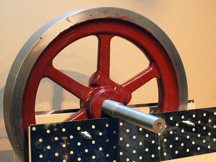 |
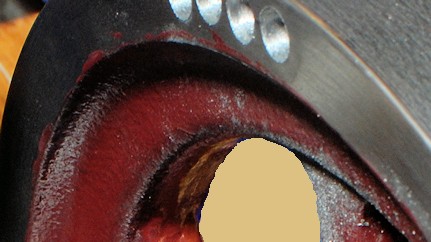
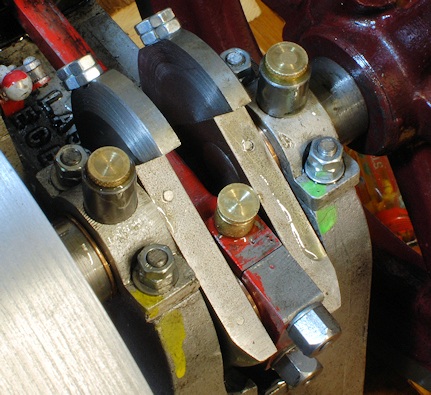
| This picture shows a balanced flywheel.
The holes were drill in the other most part as there was not much material
to the inner part. |
 |
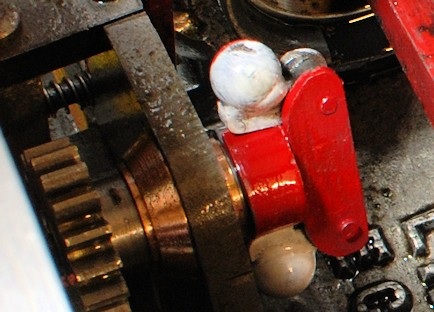
| The governor has also been painted
in contrasting colours red/ white in opposite locations on each side so that
it can be more easily seen when rotating. |
 |
| 14th December
2010
Improvement
From the run to day it was found that
the balancing of the flywheels has helped a great deal to cut down the vibration
..
Next task to balance the crank shaft
webs. Additional weight to the non big end side will be a great help !!!
Also the oil caps to the main bearings
and to the big end need a small hole in them to allow oil to drain out else
there is a vacuum created and no oil drains through. |
| 16th December 2010
Today I was able to make up the parts
to go onto the crank webs to try to balance the crank shaft a little bit.
Anything will be better than nothing.
The two balance weights were cut from
63mm round bar and then machined to 10.5mm thick and the end taken off to
allow for clearance. This was then cut in half and the surface where it had
been cut milled to an accurate datum and at right angles to the face. The
parts when then drill to act as pilot holes into the webs.
First the webs were milled to ensure
similarity and then drilled and tapped for M5 x 0.8 and the weights drilled
out 5mm as tight clearance for the M5 studding.
The crank is still out of balance but
much better.
Larger balance weights could be used
so I may make bigger ones cut from 76mm bar but let's see how these go.
I appreciate that this does not take
account of the moving masses and that will be considered in due course. |
 |
| Balancing a single cylinder
engine.
I have been told by a friend's at the
Bredgar and Wormshill Light Railway that it is a fact is that it is
IMPOSSIBLE to balance a single-cylinder engine. The best that can
be done is a compromise.
This is the suggestion :-
-
Locate a set of digital scales.
-
Take apart the crank assembly, then with
the top half (little end) in your hand level with the scales weigh the bottom
half of the rod call this BCR.
-
Now take the big end in your hand and
weigh the top half of the rod call this TCR.
-
Now weigh the piston and all that goes
with it call this P.
-
Add the weight of the top half of the
rod to the weight of piston which is TCR + P.
-
Now you need to assess 65% of this weight
which is 65(TCR + P)/100.
-
Add this weight to BCR and machine a
piece of material to this weight to fit over the crankpin thus {65(TCR +
P)/100}+BCR
-
Now you need to make weights that
balance the crank shaft.
That is the best one can
achieve.
I am guessing that if you weighed
the big end of the crank with the mass attached it would give one a starting
point as to the mass required.
I know I am re-inventing the wheel but
this is what the chaps must have done years and years ago (1910 ??)
In this article
(click for the link) in place of machining
up a piece to fit over the crank pin it gives the idea that a scale pan holding
the necessary weight can be used |
| 23rd December 2010
I have now substituted the drain bung
with a right angle 1/4" BSP male - female elbow and a bung in the end to
make emptying the water from the evaporation tank easier. |
|
|
|


 TO BE CONTINUED