The Diary of the Building of a 5" gauge Stirling Single |
|
|
|
|
|
|
|
Cylinders and pistons Part 4 |
|
| 17th September 2013
Today I was able to make up the blank ends for the steam chest to enable packing to be trapped by the use of the outer part.
|
 |
| Then the steam inlet port was drill in the steam chest in preparation for making up the steam pipe attachment. | 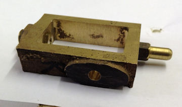 |
| The steam inlet flanges were
then machined flat on the mating side and drilled and tapped
1/4" x 40ME thread.
All the other flanges were similarly machined flat but not finished as they have different finishes to be sorted out |
 |
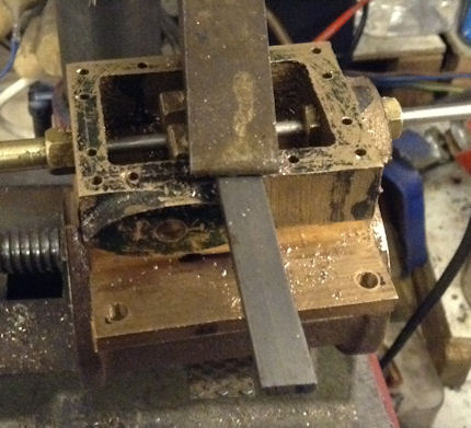
| Here the main parts of the cylinder have been stood together. Lowest part of the picture external to the frames is the cylinder and its flange which has yet to be drilled to take the pipe and inside the frames is the steam chest and the steam chest cover. | 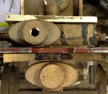 |
| 22 - 24th September 2013
The next thing to do is to drill and tap the holes to hole the steam chest and top in place. The steam chest was marked out and then drill with the tapping drill. Then the steam chest was correctly aligned with the cylinder and the holes transferred into the cylinder. |
 |
| The holes in the cylinder were then tapped 6BA first with a taper tap and then with a plug tap. I used the blue tool in the picture which I made to fit the tap and thus it is easily maintained at right angles to the hole. With all the that could be reached initially drilled and tapped the steam chest was then drilled for clearance holes and bolted down to the cylinder and the remaining holes drill and tapped and then clearance holes drill in the steam chest. | 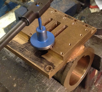 |
| Here all the bolts have been fitted through the top which had also been drilled using the steam chest at the guide to hole positions by holding the two part together with and engineers clamp. | 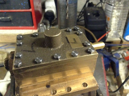 |
| Attention is now turned to the end cap. The boss which had been used to turn the read and hole it whist the piston rod hole was drilled and reamed had not to be removed and machined down to a face to external steam seal. | 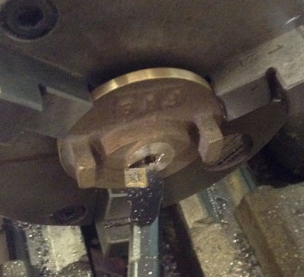 |
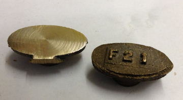
| Here the before and after pictures of the left and right hand covers. | 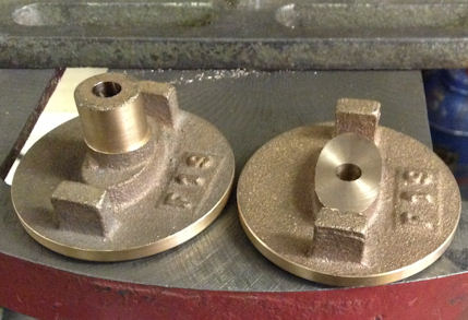 |
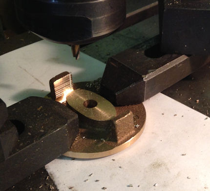
| The lands for the slide bar had to be 1.5" apart on their faces and to achieve this it was suggested that I calculate the size of a button so that a milling cutter when it just touches the side will cut away the correct amount of the seating. The photo show the milling cutter being brought up to the button and when it just touches that is the point to use for cutting the face. This was down on each side as the piston shaft must be in the centre of the two slide bars. | 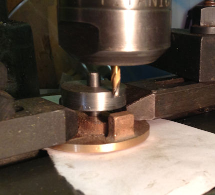 |
| The cuts achieve an accuracy
of 1.482" and error of 0.018" which I put down to the metric
conversion.
With that all completed on both cylinders it was time to have a tidy up and think about the item to do part. |
 |
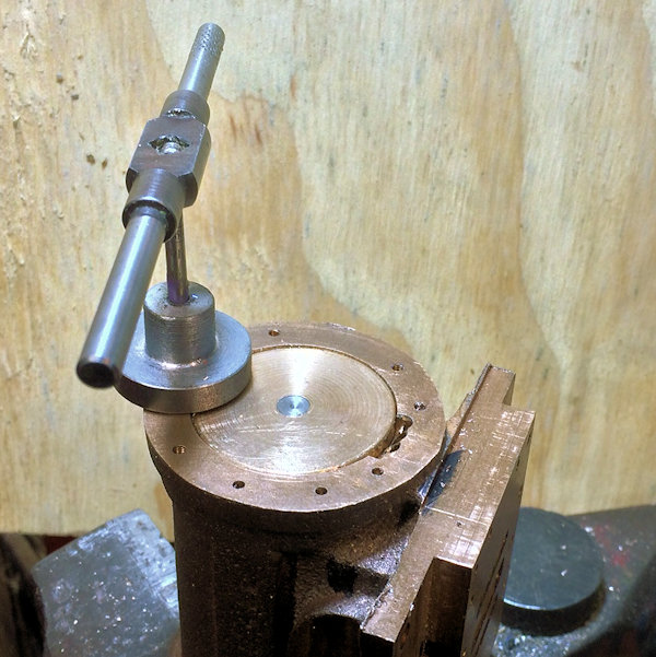
| 15th
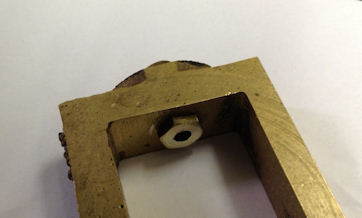
November 2015 So it is back onto doing engineering on the cylinders. I am tackling the end caps and first it is the front end as these are easier to do as I will come to later. First I had to mark out where the ports area was so to that I did not put a fixing bolt into the port and also maked where the draincock will be installed as the cylinder is not drilled and taped ready to fit them yet. First I marked out where the ten holes were to be places and centre popped and then drilled through with the tapping drill size for 7BA. Next the end cap was positioned carefully onto the cylinder to avoid the port and the drain cock position and a hole drilled and then tapped. The end cap was then drilled in this position but this time with a clearance hole. Now the end cap was again positioned onto the cylinder and a bolt put into the drilled and tapped hole. When satisfied I reverted to the tapping drill size and drilled a hole opposite the first one, tapped, and drill out bigger the end cap and put in position a second bolt. The picture shows the tapping guide which I made up to keep the tap entering into the hole square with the end of the cylinder. I was pleased to be using a new 7BA tap as it entered the casting very nicely thank you ! |
 |
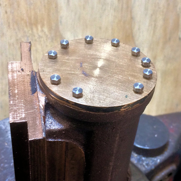
| Satisfied that the two
bolts were in the correct places and the end cap secured the
remaining 8 tapping holes were drilled, tapped and the end cap
then opened out with the 7BA clearance size drill. Some re-tapping of holes may be necessary / shortening of bolts to make then pull down tightly on the end cap - a job for another day as tis one end cap fitting took over 4 hours to complete.. |
 |
| 27th October 2017 Today I decided to go back to the cylinders and complete the unfinished work of November 2015. The end cap of one of the cylinders need to be drilled to take the 5/16" piston rod. The end cap was carefully aligned and drill through 7.5 mm and then reamed 5/16". Both need to have the 5/16" x 40 threads lengthened by 1/4" or 10 turned of the die. A check by holding the connecting rod adjacent to the wheel indicated that the distance of travel is fine. Next I have to cut away the excess steel on the guide rods to allow the connecting rod room and also fit the little and bush and drill and fit the holding part. |
 |