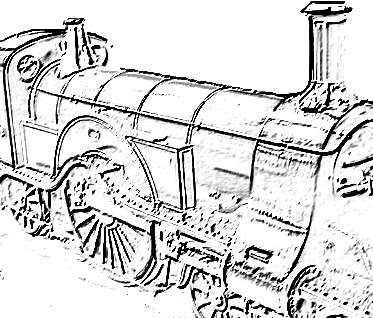
The Diary of the Building of a 5" gauge Stirling Single
|
|
|
|
|
|
|
Erecting the Main Frames |
|
| 18th July
2007
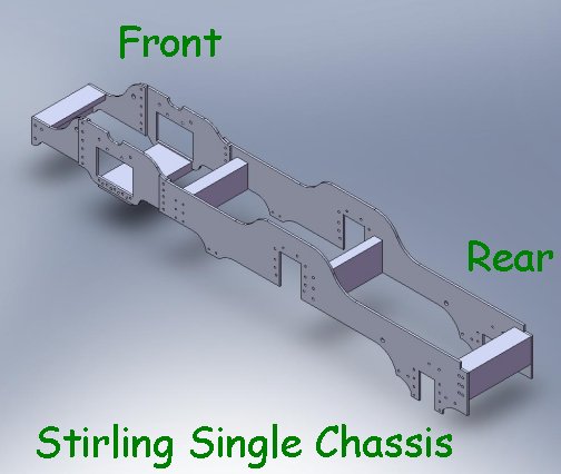
A bit of a lul in the construction due to holidays but now I have been introduced to 3D modeling. This has resulted in the picture below which shows (approximately) what the chassis will look like when the frames have been erected. |
|
|
|
| 8th Jan 2008
So the workshop is cleared and the frames have been found along with the stretchers and drag beam and work can again start in earnest. |
|
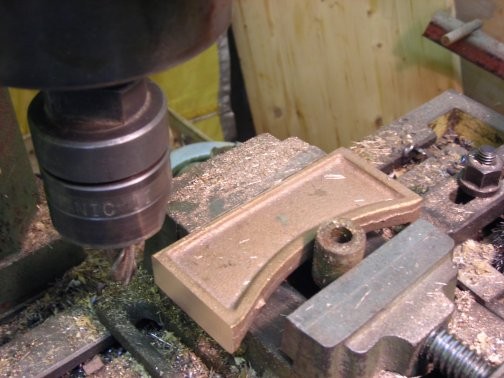
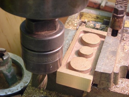
10th Jan 2008 Today saw the real re-commencement of the engineering with the machining of the front drag beam. I am working in mm so everything has to be converted as the drawing is in inches. Then followed the Centre Frame stretcher, as shown in picture on right, and the rear drag beam. The trailing horn blocks castings were tidied up ready to be cut in half and fixed to the frames.
|
|
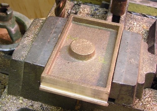
11th Jan 2008 An afternoon start and only a short time as supper party later. The motion plate, as shown in the picture on right, was the first part to be machined followed by the Front Bogie stretcher, shown in the picture below. On both these part other machining will be necessary. 16th Jan 2008 Machining of the trailing horn as shown in the picture below on the right. |
 |
|
 |
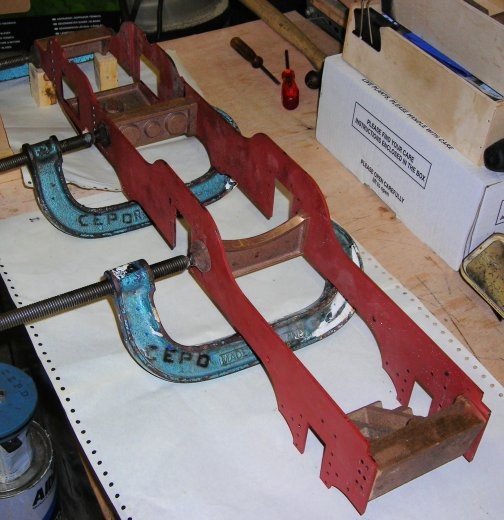
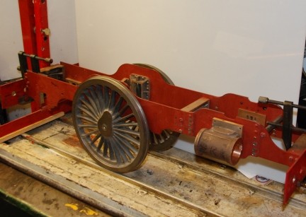
Here the frames are standing with stretchers etc in place. The next job was to rivet into place the horn blocks. |
 |
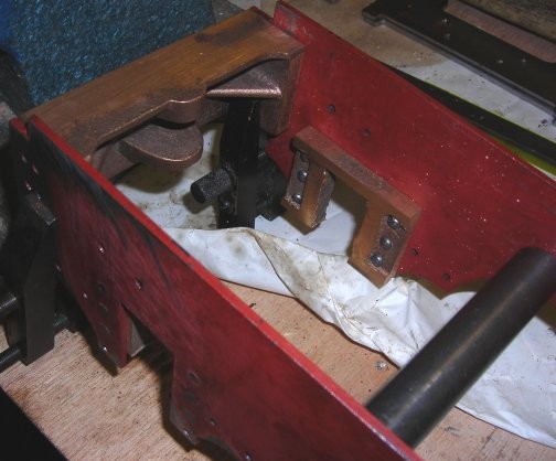
| From the picture above right the assembly now has temporary spacers that I hope will hold everything in place whilst the holes are drill and tapped to the M4 countersunk bolts. The plans show to use 4BA but it seems that there is a change fast approaching where the BA bolt will be a thing of the past so I thought better to change NOW! | 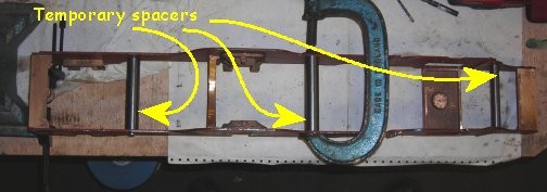 |
In the picture you can see the rear drag box held in position with machine tool makers clamps ready for the holes to be drilled and with the trailing horn blocks in place. |
 |
| The picture shows the front drag box and behind that the bogie stretcher. Work still has to be carried out on the bogie stretcher before it is ready for final fitting. | 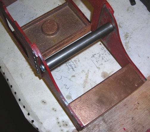 |
20th Jan 2008 All the frame separator have been machined and fitter.
|
 |
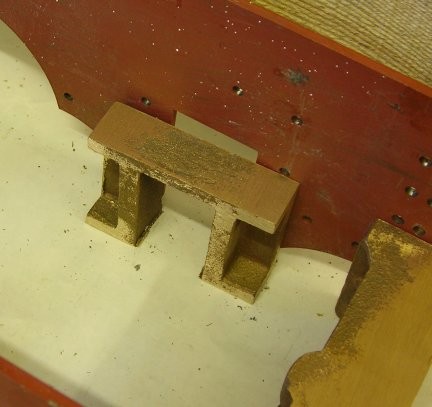
| The Front Bogie support stretcher. | 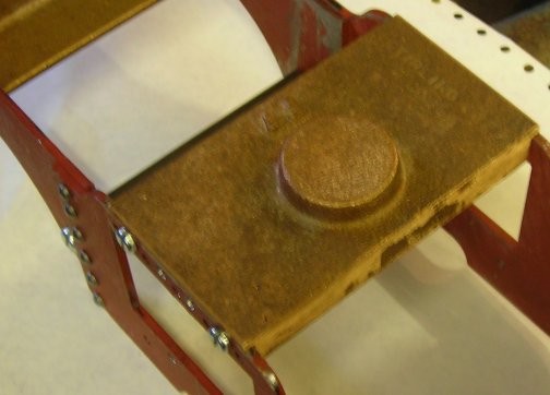 |
| The Motion Frame, there is still much more work to be done on it. | 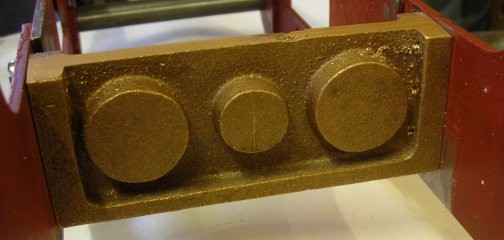 |
| The frame that site under the Boiler. | 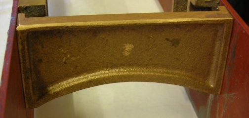 |
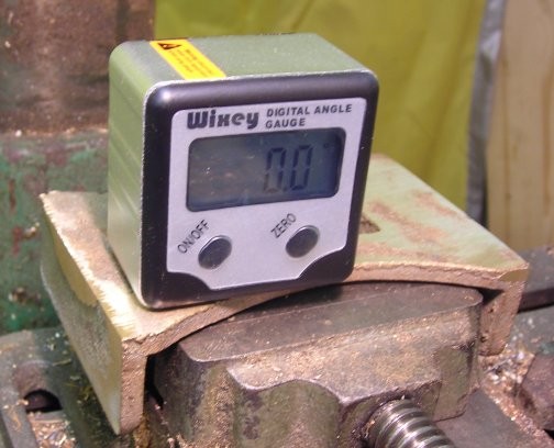
| 21st Jan 2008
The "Wixey" a fabulous item that will reset to the level status of your equipment as the datum and thus you can find out if the part to be machined needs packing to hold it in place properly.
|
 |
| Here the fames for the sides of the bogie have been fitted to the bogie stretcher and just placed for the photo under the main chassis. | 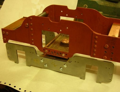 |
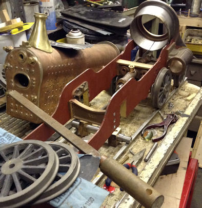
| 23rd July 2010
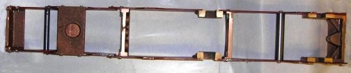
The frames have now been mounted on the work bench where they can be built up as parts are made. |
 |
| 13th September 2013
After a long break away from engineering today I started work on the list of
things that a close friend told me I must do to complete the loco.
Firstly the boiler was taken off the loco and is to be put safely away and a
general tidy up so that work can progress.
|
 |
I was told "Make sure you have all the frame stretchers in place especially the front bogie stretcher which all have to be fitted with countersunk screws." I also had a temporary stretcher at the front which will now be soon removed. A drill was sharpened to the correct angle for a counter sink / counter bore to take the M4 socket countersunk bolts. |
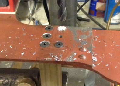 |
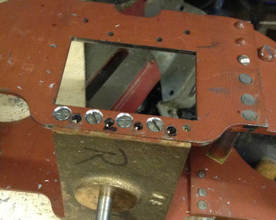
| All the M4 bolt holes were counter sunk and bolts fitted.
Following that the 4BA bolt fixings were drilled out and tapped 4BA the necessary countersink made on the frames and the 4BA bolt screwed into position. |
 |