The Diary of the Building of a 5" gauge Stirling Single |
|
|
|
|
|
|
|
Completion of the build Part 15 |
|
| 30th
September 2019 Piping up the pressure gauge. Whilst the fitting to the manifold was easy enough to make fit with a nipple, the end for the gauges had to be widened out a little so the the back end of the nipple could enter the pipe and then silver soldered without messing up the union. It was then put in the acid bath for 45 minutes to clean it up and given a polish with Brasso, The pressure gauge has to be marked "with a red line" at the 80 PSI position but to do that I need to go to the club and use the calibrated gauge. |
 |
|
1st
October 2019
Working
on the pipework from the was proving rather difficult so the
only solution was to fix the manifold in place.
6BA
fully threaded bolts was shortened to make suds and these were
screwed in to the boiler.
Some
Blue gasket sealer was applied as a thin coating to the base
of the manifold which was put over the studs, nuts fitted and
tightened down BUT NOT FULLY. After a few minutes as tyhe
instruction indicated the nuts were tightened down further to
give I hope a seal but I will not know that until the pressure
test is done.
|
 |
| The
next difficult part to achieve was the blower pipe which passes
through the boiler and held in place by threaded union as each
end. A thinner coper tube which fitted inside the blower pipe
was used to lead the way for the blower pipe into its union. Loctite 542 was used on the threads at each end but not on the banjo bolt ! The banjo bolt just was used to make sure the pipe was screwing into the fitting the far end and the backhead side tightened down. In due course the Banjo fitting will be sandwiched between two copper washer suitably annealed to make a steam tight union. |
 |
| 2nd
October 2019 With a decision to revert to the use of the boiler fill bushes at the front of the boiler a method to access the clack was required should a repair / replacement be required. With the help of Martin, a boating / engineer friend, we devised a cunning plan to hole the side piece with a long bolt which is hidden under the valance. The photo shows the inside. The bolt is a piece of 1/8" p Bronze and is threaded each end 5BA. The top was then soft soldered to retain the bolt which was screwed into a tapped hole. Location rivets were soft soldered into the two of the holes where previously fixing down bolts existed. |
 |
| The
bung was removed and the holes cleaned out using a 1/4"x40 tap.
The clack was then screwed into position. Pipework from the axle pump will be connected. |
 |
|
3rd
October 2019
Piping up the Axle pump to the boiler clack on the side of the boiler. This take a very tortuous route as it is very tight under the boiler and close to the eccentrics and the reversing arm. The Tee piece could not be at right angles to the frames as the pipe work would have fouled the eccentrics so decided to put it at an angle to ease the bends.
I first made a lead trial to see what the bends looked like
and then made it i5/32" copper pipe.
The
previous stop end to the pump was utilised as the fitting to
the pipe by drilling a 3/16" holes through and used a 1/4"
slot drill to made a flat bottom, lastly the excess amount of
brass was machined as to make the final union nut.
The
pipe has two nipples silver soldered into place with the nut
put on first ! After all the annealing and bending to shape
the pie was put into Kill Rock for 45 minutes to remove the
copper oxide and leave it looking better.
|
 |
| To
be able to mark my Pressure gague with a red line at the working
pressure I needed to have a fitting that would mate with the
Club's Pressure gauge so the photo shows what I have made up. It
takes the pressure gauge which has a 3/16"x40 thread and the
club's gauge has a female 1/4"x40. and thus the link was made
with male 1/4"x40. . |
 |
| 4th
October 2019 The blower pipework was completed by joining the outlet to the front of the boiler. Final shaping will be necessary when boiler is installed to make sure the blast from the pipe goes up the chimney ! |
 |
| The
blow down valve has a square key end and for quite some time I
have been thinking as to how to make a suitable key with a
square ended recess. I decided to make it out of 1/4" pipe and
use a drift of square steel the same size as the key, put a
taper on it and then annealed the copper tube and gently
hammered the drift in to the tube re-annealing and more
hammering as necessary until I was happy with the result. It is a great fit on the blow down outlet which is sealed with an "O" ring so no great force will be required to operate the key so a small bronze cross piece was silver solder into a suitable drilled hole. The fitting cannot be pout in place until the boiler has been mounted on the loco else it would not be possible to actually mount the boiler !!! |
 |
| 5th
October 2019 123 days since the loco completion
re-started. Not easy to see but the feed from the tender now is linked to the axle pump it follows the line of the frames at the top of the picture. So many bends and a couple of bends as kinked the pipe and also had to reduce from one size to another !! . Between the engine and tender a flexible rubber pipe will exist as the water feed is not under pressure. |
 |
| Having
made a mistake on the pipe size for the injector a new one was
purchased. |
 |
| As
the pipe work is now 5/32" and not 5/16" a new water inlet
fitting was made having a 1/4"x40 thread and the pipe work was
formed to go over the training wheels following the line of the
water feed for the axle pump. A few more bends are required when I have decided where the injector will finally reside ! |
 |
| 6th
October 2019 The pressure gauge is an essential part for the loco and a RED line has to be applied at the working pressure of the loco which in my case is 80 PSI I visited MMES today and was able to use the club's boiler testing pressure gauge to check the calibration of my gauge. It all tested out well and the Red line was applied |
 |
| The photo shows the
part fitted injector. final straightening up and the putting the
pipe in the Kilrock to clean up to be done before polishing to
make it look nice. The last pipe to be fitted to the injector is from the steam valve on the turret which needs the boiler to be fitted to the frames. |
 |
| The final two clack
valves installed with Loctite 542 so the boiler is ready after a
final check to be installed onto the chassis. |
 |
| 7th
October 2019 Before I could proceed further I needed to make a reducer nipple as the one from the tender pump assembly was too big. The part was made as discussed at the MMES club yesterday |
 |
| I checked the diagram
of the injector and realised my mistake of working upside down
that the injector was in fact back to front. This is now
corrected with the water in on the same side as the steam in!! |
 |
| This is the underside
pipework at the rear of the engine. The unconnected pipe fitting is for the bypass which I hope to tackle tomorrow. |
 |
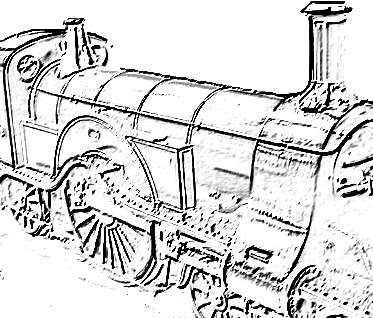
| So here is the loco so
far. I have found :- that the reverser binds on the wheels and boiler so that will need to be skimmed down a little As the driving wheel go round there is a "click" so need to investigate the cause and remedy Things to do :- The pipework in the smoke box from the super heater need to be coupled to the unions to the steam chests. The covering of the cylinders needs to be completed Automatic drain cocks need to be made and fitted |
 |
| With the boiler
removed I was able to see how to couple up the bypass valve.
very tight space indeed by so far so good. A small amout of the
left have frame need to be cut away to allow the pipe a gentaly
traverse and without touching. All the pipework needs to be clean in Kilrock and then finally fitted. |
 |
Next Page |
|