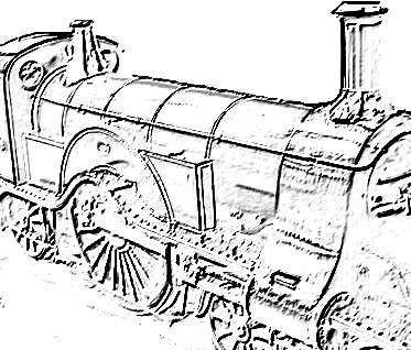
The Diary of the Building of a 5" gauge Stirling Single |
|
|
|
|
Frames - Wheels |
|
|
|
|
| Now construction re-starts in 2007 with the main frames then the frame stretchers and then the main axle horns. | |
|
|
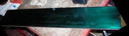
The material for the main frames with "Spectra Blue" applied ready for the marking out - which as you will see below was not needed!!! |
|
|
|
|
Mention has been made to me to increase the cylinder bore to 1 1/2" to 1 5/8" else the loco is a little under powered. This would require Maid of Kent cylinders being obtained. I have decided to build with the existing cylinders as they were given to me by my mum. |
|
|
Oak is required as a fitting between the front buffer beams of the loco and the read buffer beams of the tender. A friend, John Mallichan, has kindly donated a lovely piece of Oak duly signed by him so for posterity if the loco were taken apart his signature would still be there. Thank you John. |
|
| Sunday 4th March 2007 I took a trip to the National Railway Museum in York and I took many photos of the No.1 Stirling single on display. They I hope will help with the detailing of the loco. | |
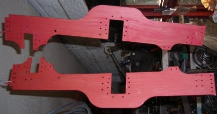
| Wednesday 7th March 2007
My son in law introduced me to CAD design and by Friday 9th
March I had drawn up the frames of the loco and taken them along
to the CNC laser cutter which is local to me.
Here you can see that they have been painted. They are in fact in three parts each side which is necessary to enable the "narrowing" in the frames to be achieved without resulting to bending the frames. |
|
| Wednesday 13th June 2007
To-day is the day the that frames finally were riveted together. First a counter sink was drilled to allow a very small amount of parallel material then the countersink to aid with strength. |
 |
| Rivets put in place ready to be cut off. | 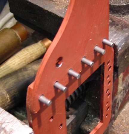 |
| Cutting off the rivets leaving just enough to hammer into the recess. | 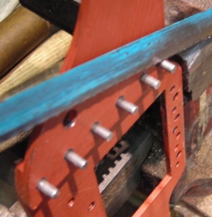 |
| Note the use of the "dolly" beneath the snap rivet head to support whilst the other side of flattened. | 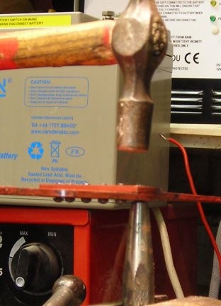 |
| Rivets flattened into place. | 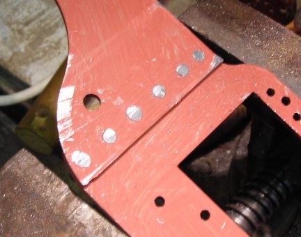 |
| Rivets filed off flat. | 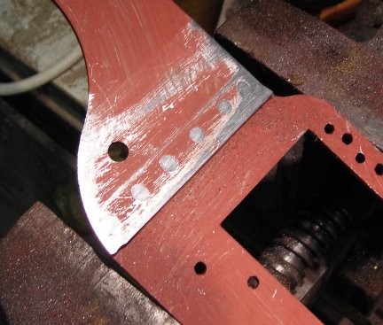 |
| Both frames riveted up ready for the horn blocks to be rivets into place. | 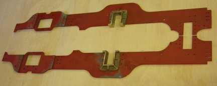 |
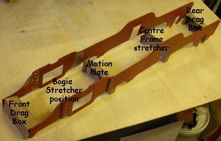
| 15th June 2007
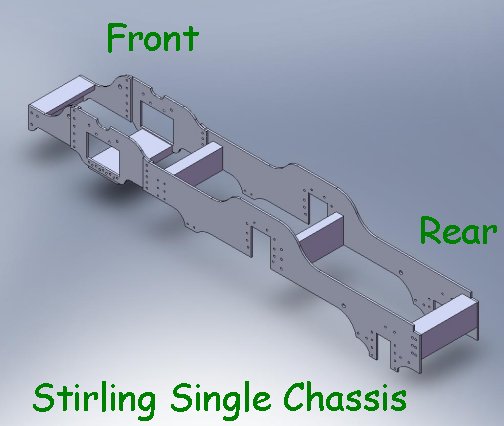
The picture shown the frames and the various stretcher and drag boxes. I have identified that I do not have the bogie stretcher. So that will be ordered!! |
 |
|
|
|
Wheels |
|
|
Saturday 19th May 2009 A start was made on the loco wheels. The backs of all the wheel except for the main driving wheel was achieved but I have no way to hold the driving wheels in the lathe. I have since doing this machining been told by a person with more experience than I that should have followed this order of machining:-
So with this in mind please forgive the wrong method and may be when I checked I may have to buy a new set of casting of the driving wheels !!!! |
|
| Here are all the backs finished except for the driving wheels. |
|
| Monday 21st May 2009
Much of the day is taken up with my pottery class but the afternoon saw the finishing off of the basic turning of the 6 wheels leaving only the final bringing to overall size and providing the flange detail. Later on Monday I made up CAD drawings for back plates to be used on the lathe to mount the wheels and emailed the drawings to the laser cutter.
|
|
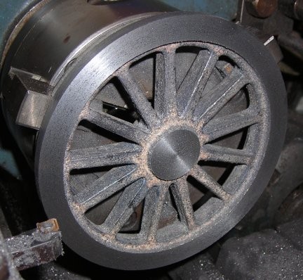
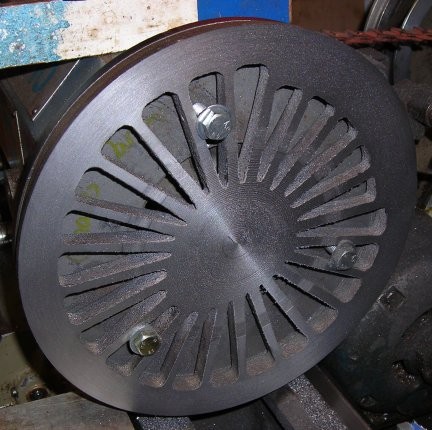
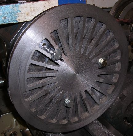
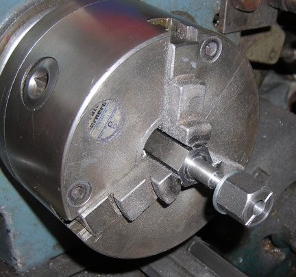
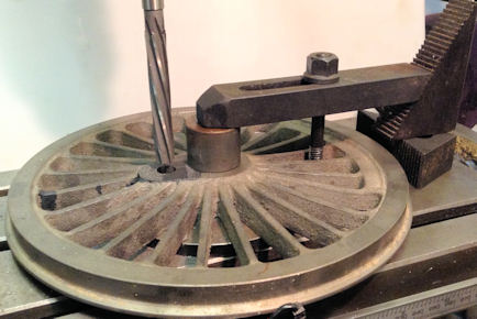
| Tuesday 22nd May
Tuesday morning I received a telephone call from the laser cutter to say that the disc were all cut and ready to collect. The picture shows that the plate was mounted on a face plates and then three 8mm bolts held the wheel in place. This wheel has a diameter of 9.5" 241mm so it is quite the largest item I have turned in the lathe. The two fixing holes were made as far apart as possible as there had to be a hole in the plate to allow the boss on the other side to stick through!!!
|
|
| It never was possible to
make a cut right across the back of the wheel due to the bolt
positions.
For the second wheel I will see if the bolts can be positions better to allow a full single final pass as it would make the machining so much easier. |
|
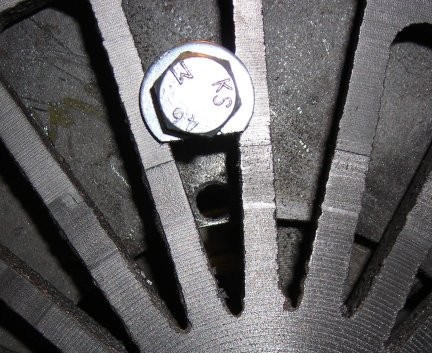
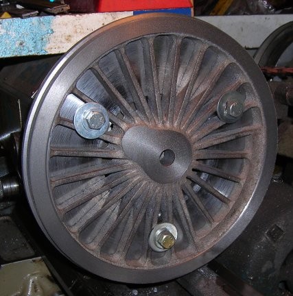
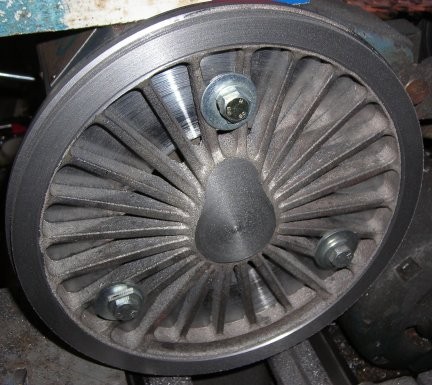
| The picture shows the bolt
and the alternative fixing position.
I will be drilling and tapping three new holes further out in an effort to allow after a change of holes the cut could be continued right across the face of the wheel. Still it could have been a whole lot worse and the picture actually enlarges the surface imperfections!!! |
|
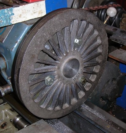
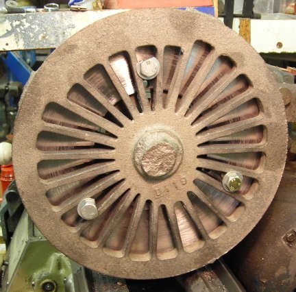
| And so to the second driving
wheel.
This picture shows how it started out as the casting with a very larger hub you machine away. |
|
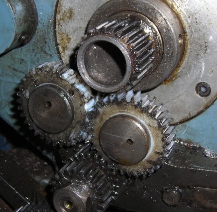
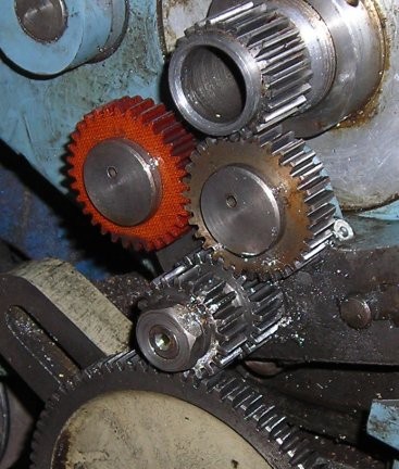
| All was going very well
taking about 0.5mm cuts with the power slide when suddenly no
drive to the power cross slide.
After nearly ten years of off and on use the reversing gears were torn to shreds. As one gear was stripped so the other gear must have stripped. These gear as purposely made of nylon / tuffnal so that and excess of load shatters the gears and does not damage the main spindle gear or those in the gear box train - well that's my story but I have been told it is not the case and they are made of tuffnal so that they will run quietly !!!! I have replacement steel gears but I only use those to complete a process which I did in this case and am trying to order replacements but failing that as with these I shall have to cut my own gears.
|
|
| So for completeness here is
the second wheel with the rear side completed.
Until the new gears are cut the turning will be by hand on the cross slide !!!! So the first thing to do now is make up the blanks for the new gears and get cutting !!!! What a shame I did not make spares ready for use - fine being wise after the event!!!! I have now located a web site which can supply the gears and they have been ordered. |
|
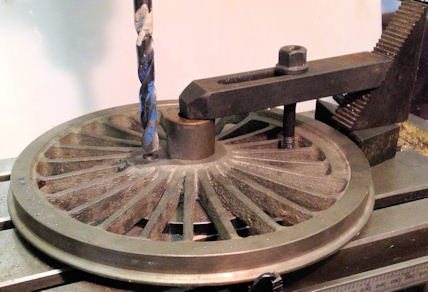
| Wednesday 30th May 2009
The new gears for the lathe arrived but as I had only one bush I fitted the gear and left the other gear as steel. The back plate was reduced in diameter by 1mm and then I commenced to cut the front face of the main driving wheels and bought it to thickness. Consideration has been given to the purchase of a reamer to cut the finished hole in the wheel for the axle but as it will only be used twice I have decided to use a new 9/16" drill but to first drill through with a much smaller drill and work up so that the final drill cut will be very small this will make the axle hole 1/16" small in diameter than to plan but will allow the job to proceed. |
|
| Thursday 31st May 2009
An early start at 07:00 and progress on machining the centre boss and drilling the 9/16" hole went well so much so that I have decided that I will buy a 5/8" reamer and complete the job fully. The reamer should arrive in the next few days ... |
|
| Friday 1st June 2009
The 5/8" reamer has arrived. I bored out the hole that had been drilled to about 0.4mm and then used the new reamer to complete the hole. A very nice job it made too. |
|
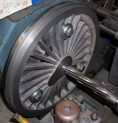
| Then I continued with the
second wheel which was first brought to the correct thickness
then a spacer used which was 1mm wider than the distance between
the thickness of the wheel and the hub.
With the rear stop adjusted to the spacer thickness the cross slide was wound in 1mm the turning of the centre could commence until competed. The outer edge and tread were then skimmed of the outer casting material and the wheel is ready to drill - bore and ream.
|
|
| Saturday 2nd June 2009
To finish off all the wheels arbours will be made to suite the size of axle hole and a large nut used to hold the wheel in place and the turning carried out very gentle. The arbour shown was for the small wheels -the only difference to the arbours for the big wheels was the diameter of the part for the wheel to sit on and the size of the thread. Each cut is carried out to each wheel so there all end up exactly the same size !!! This does mean that the wheels are put on and taken off the arbours several time so it is well worth making a good fit to the wheel / arbour but not over tight. I have a tipped tool I use for the final finishing cuts including setting the correct 20deg angle between tread and flange. The tool is put in the cross slide after all the wheels in the set have been brought to size the angle to the flange is then cut. Thus is only used for very light cutting. The tool is brought up to the flat face side of the wheel and clamped then the cross slide is turned through 20 deg and adjusted to take the lightest of cuts across the wheel and then cut the flange. |
|
|
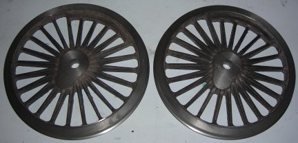
Here both the driving wheels are fully machined and only now need the crank pin location to be drilled and reamed. |
 |
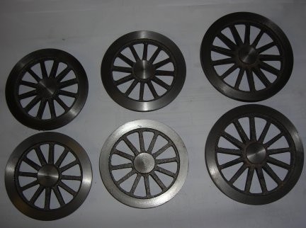
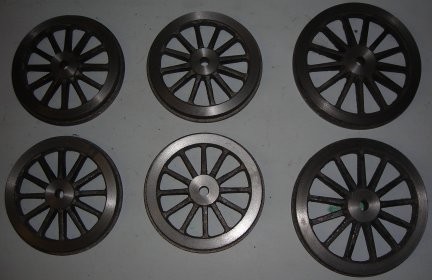
| The complete set of wheels for the loco. | 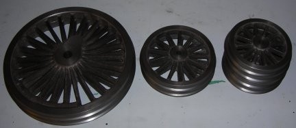 |
| 29th July
2009
I have received the following advice ( in red text) regarding the crank pins. The main idea is to get all the holes as near as possible the correct distance apart. Using a milling machine with a boring head (or it could be done with slots drills and reamers) you could do it in the mill as follows:-
The former tools will not give such a good finish to the hole but it depends as to how you intend to fix the pin..i.e. either a push fit or one of the modern 'glues'. The latter method requires clearance in the hole for the glue anyway so surface finish is not so important. The main object of the exercise is to get the holes all the same distance apart and vertically square with the wheel. It will not matter so greatly in your case as you only have one wheel. but if you have coupled wheels and the pitch of the holes are not the same you will have trouble getting the connecting rods to run without excessive clearance in the bushes. |
|
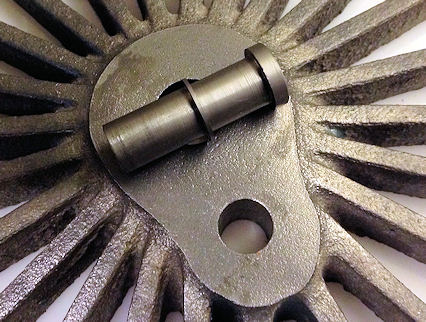
The jig in the picture is the one used by Roy O'NEILL when machining his crank pin holes in a lathe. The groove between the two holes is done for a keyway alignment. Roy's wheels are keywayed.
|
 |
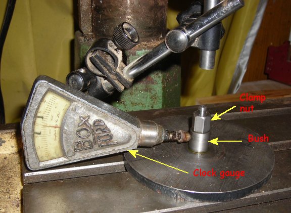
| 30th
July 2009
If you are using a milling machine can I suggest that before you start to do any checking of the location of the clamping parts assess the position of the "Z" axis to ensure it is correctly positions to take the drills / reamer you may wish to use and then lock its position on the mill. Then the only part that can move vertically is them main cutting head. Failure to do this may result in inaccurate positioning. So I have now turned a bush to fit the centre bore of the wheel making certain it was a little shorter in length than wheel thickness. Then I drilled a hole down the centre of the bush and made up a milling clamping bolts to pass through. I could not use the mills own clamping set as the centre hole of the wheel was too small! Above the table I placed a section of metal that can be drill into through the wheel and clamped that and the bush to the mill table. I adjusted the location of the table directly under the centre of the spindle by eye then made final adjustments by running a 'clock gauge' around it. Please excuse the old "Boxford clock" but it is all I have and goes with my old Boxford ME10 Lathe! Then the 'Y' axis (front to back movement) of the machine was locked. |
 |
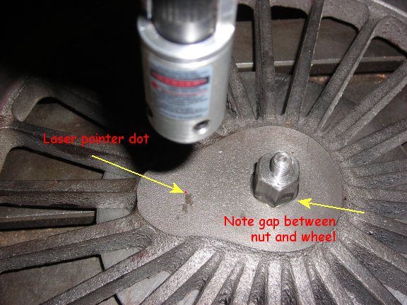
| Using
the graduations on the mill the 'X' axis (left and right') was
moved the amount required for the distance between the centre
of the axle hole and the centre of crank pin hole and the
table locked in that position.
The distance moved was then checked by using a laser pointer set into the drill chuck and digital calliper to measure and thus check that the position was correct. From now on the table will remain fixed until all the drilling and reaming is completed.
|
 |
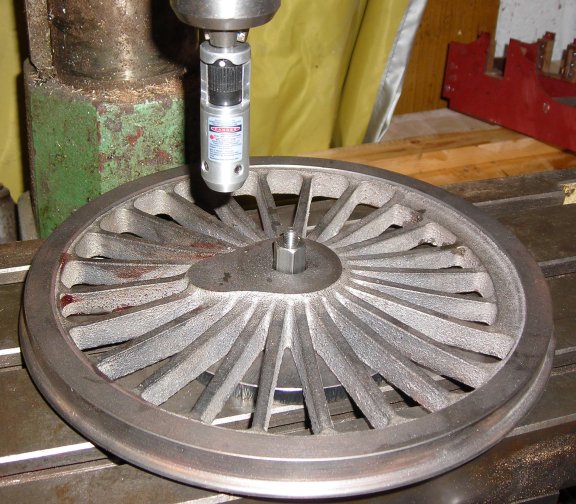
| All I
now need to do is pop the wheels in turn over the bush
ensuring that the lobe on the wheel aligned with the centre
line along the 'X' axis and clamp down securely so that it
does not move during drilling etc.
The wheel is in place by not yet clamped down !! That will wait until another session in the workshop as the total time to achieve this far has been 4 hours - may be I am just a very slow worker. |
 |
| I have also made up a cover for the clamp so that the clamping down gives uniform pressure to the centre of the wheel and there is then no chance that the wheel might tilt. | |
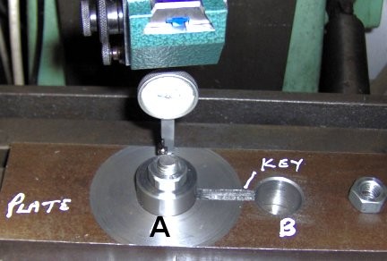
| 22nd November 2013
So after 4 years it is time to drill the crank holes. Because of the time delay I did not actually leave the wheel set up but today followed the instruction through exactly as are given above. To double check that I had the crank in the correct place I made up a spacer exactly to measurement and used it with an engineers clamp on the cross slide to move it to the drilling position. I also marked the wheels where I expected the point of drilling to be and check that with the laser pointer in the drill chuck. When satisfied it was all correct the hole was drilled |
 |
| Then the reamer at size was
put through the drilled hole.
It was very satisfying to find that my notes on the web site were so useful even for me to set things up again and successfully complete the whole task in about 2 hours. |
 |
| 24th November 2013
The crank pins were made to size. |
 |
| They were then fitted with engineering adhesive Loctite 601 | 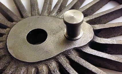 |
| The next item will be making up the big end bearing to this modified drawing. Click here to move to the next page | 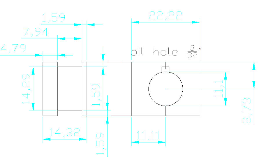 |
| Late
October 2015 I decided to make an effort with the parts that will keep the wheel in place. First it was the main driving wheels |
 |
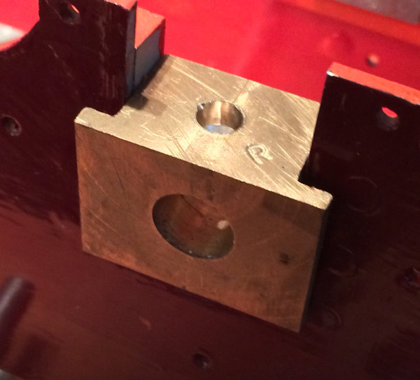
| Here the oil ways have
been drilled in the main bearings |
 |
| Here everything is sorted out and in fact ready to prepare for painting. | 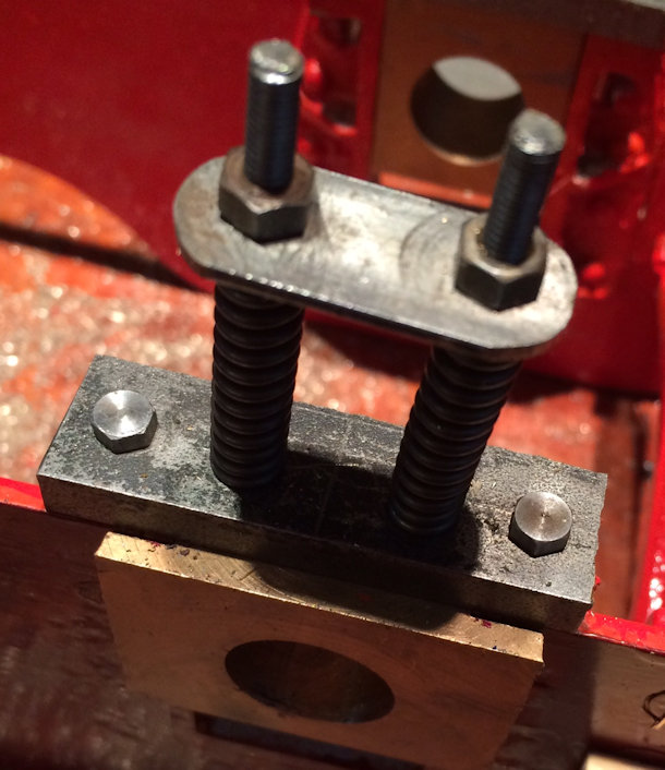 |
| In the photo the trailing wheel set is completed . | 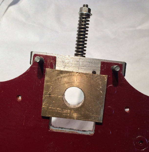 |
31st October 2015 Today I made the keepers for the bogey, the keepers bolt still have to be cut down. |
 |
| 1st
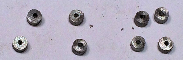
November 2015 To day I started to make some of the smallest parts I have ever made. The little brackets to hold the axle springs. The holes in the bogey are 1/16" to take small rivets. |
 |
| 2nd
November 2015 Today I was able in the absence to the correct size bar to machine up the spring bolts for the bogey, |
 |
| The workshop as of today | 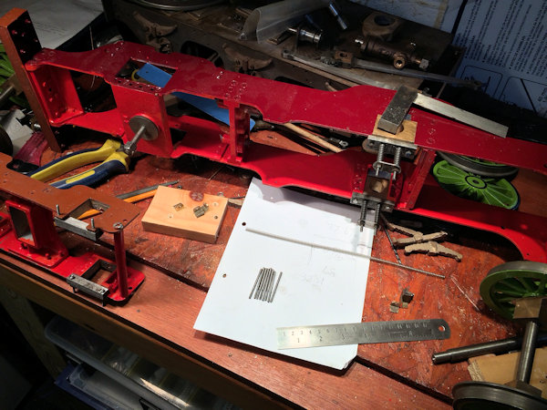 |
| 3rd
November 2015 some small bits to go with the parts made yesterday |
 |
| 5th
November 2015 The threaded rods and the round pieces are now silver soldered together |
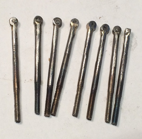 |
| I decided to do 2
hours more work in the evening rather than watching the TV The result of the evening is that I was able to fit and rivet the 8 angle brackets to the bogey. Each angle piece had to be fitted to align the hole in the angle with the centre of the holes previously laser cut into the frames. |
 |
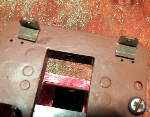
| 6th
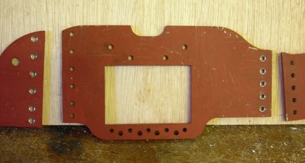
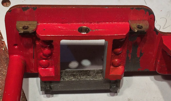
November 2015 Following showing my efforts at my local model engineering society I learned that the caste leaf springs would be likely to foul on the main frames and alternatives were discussed and resulted in what is shown here from the under side . |
 |
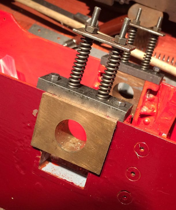
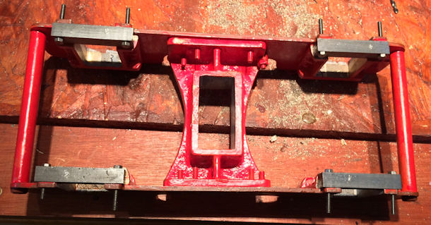
| This photo shows the
top of the spring arrangement Not having and solid bar the right size the top part was cut from 1/4" x 2" steel and then drilled and tapped to take the spring holders and the little pin that pushed down on the axle box. All threading was then locked with Loctite 603 adhesive. I have to buy bigger springs as I do not have 8 all the same size ! I will order them in due course and retro fit ! |
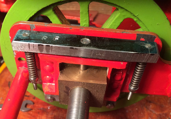 |
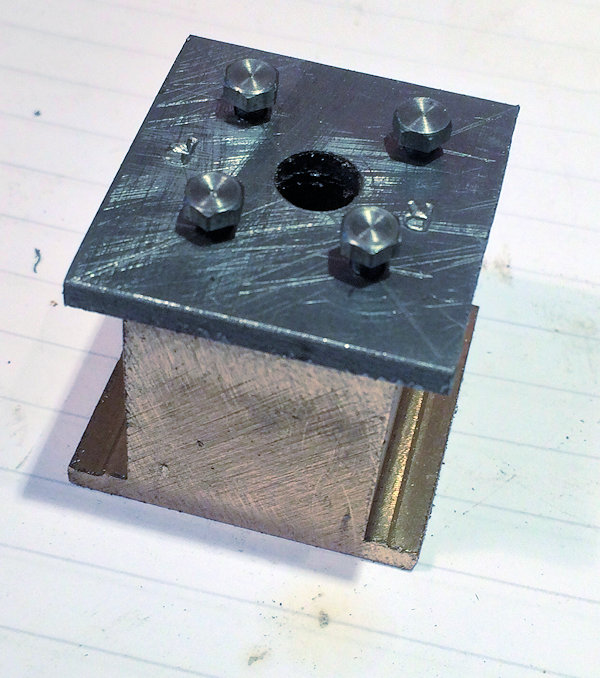
| 8th
November 2015 The centre slider had to be completed by machined to size and then fitting the steel keeper which is held in place by 4 6BA bolts into tapped holes. |
 |
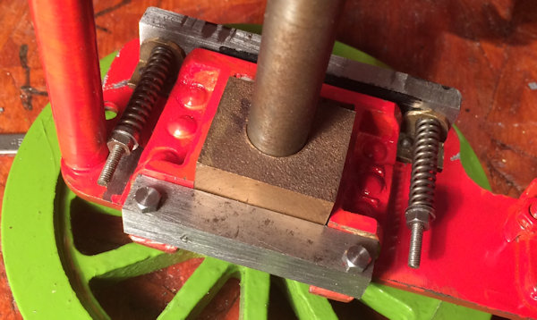
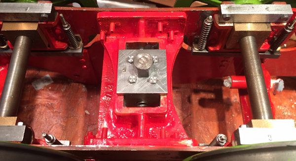
| 10th
November 2015 The front bogey is now fixed in place. I hope you can see the springs which are used to centralise the bogey when the loco has gone round a corner. |
 |
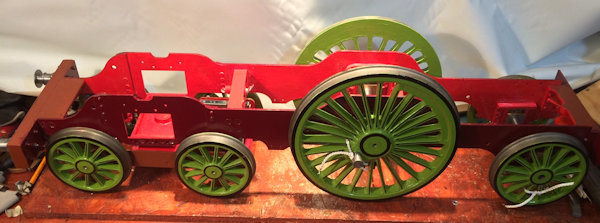
| So the frames are now
on all the wheels even if they are not all fully fitted, for the
first time and thast completes this section. |
 |