The Diary of the Building of a 5" gauge Stirling Single |
|
|
|
|
|
|
|
Valve gear, axle pump and reverser |
|
| 13th July
2010
With the cylinders all but finished it is time to consider the steam chest and valve gear. I found this site which shows a nice animation graphic of the Stephenson Valve gear such as is use by the Stirling Single. Click the link to see it in operation |
|
| 18th July 2010
I was able to machine the two valve chests to thickness and face the locations of the steam entry and the slide valve, |
 |
|
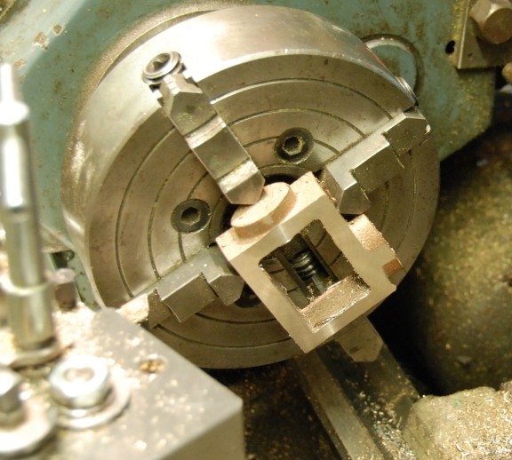
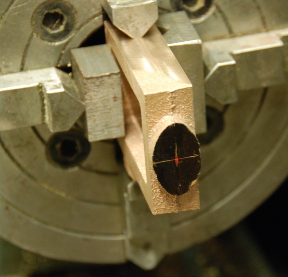
20th July 2010 Today I was able to mill the steam chest ready to drill the steam entry point. |
|
|
This is the set up in the lathe with the laser pointer lined up on the cross marks. |
 |
|
Here is the valve with its base and port machined and on the other side but not shown the recess for the valve spindle. |
 |
|
21st July 2010 I have had to machine off another 0.5mm from the face of the valves leaving only 1mm of material else I did not have any free play between the valve spindle and the valve to allow it to float. I still have to machine the drive cross piece but things are at least encouraging me to go further. |
|
| 2nd August 2010
This evening I was able to machine the two valve spindles bearings and set them into the cross support. |
|
|
6th August 2010 The files for the various parts for the valve gear were sent to the water jet cutters in Staplehurst. |
|
| 26th
September 2013
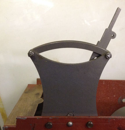
So after more than 3 years when the parts were made I have made a return to the reverser. This was put together from the water jet cut parts. |
 |
|
10th August 2014 So four years almost to the day when I received the water jet cut parts work was carried out to join the pump eccentric to the link which will drive the pump in and out. A former was drill for the bolt centres and the tapping and clearance drilling carried out as necessary. The holes in the eccentric were tapped 6BA. The necessary 4BA holes were drilled and tapped which will lock the eccentric to the main wheel axle. |
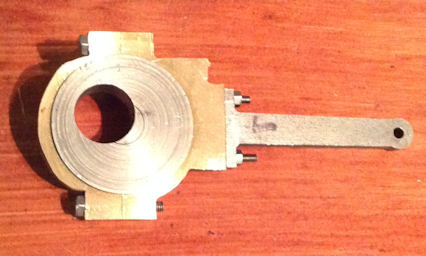 |
| 10th
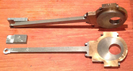
August 2014 Work also commenced on the valve gear linkages. Using the same template the first two arms were attached to the eccentrics again with 6BA bolts. |
 |
| 11th
August 2014 The remaining two eccentrics and their arms were attached. All four pieces were then milled out to allow the expansion link to sit in the centre of the arm. As the thickness of the main part was too thin a secondary part is being made that will be cut to shape, drilled in preparation for installation. |
 |
| 12th
August 2014 The additional piece seen set beside the arm in the photo above were riveted onto each of the four arms. A set of filing buttons were made up and the ends filed round to match to main part and the excess on the sides milled and filed away. The bolt through the top of the expansion link is there merely to hold it in place for the photo. |
 |
| 13th August 2014 More materials purchased today and the four pins to link the eccentrics with the expansion link were made from Silver Steel together with four 05.mm washers. So no picture as very little change from yesterday. |
|
| 15th
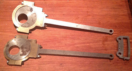
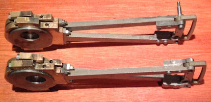
August 2014 I made checks on the valve gear and found that the profile of the rear part of the eccentrics were not to size and also the front of the eccentric was 4.9mm too big so it fouled the valve slide fitting. The item on the left hand side of the top photo was used as a filing sizer so the the rear of the eccentric strap could be easily brought to size. The item on the right of the top photo was used to accommodate all four eccentric straps and then enable them to be milled down by 4.9mm on the front bolting edge. The lower photo shows the eccentric straps of one pair all brought to size and everything fitted. |
  |
| 23rd
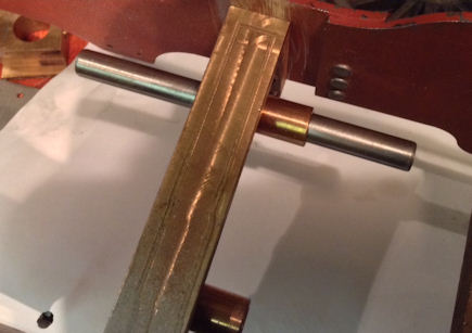
Sept 2014 Today I decked to check that the rod I had purchased fitted the renamed hole for the valve gear. It did not so the cross piece was removed and the reamer put through the holes again and to entrance to the holes both end had the sharp edges taken off. Then the rod would go in but very tight. A light application of wet and dry to the rod soon fixed that so the it was a nice sliding fit. |
 |
|
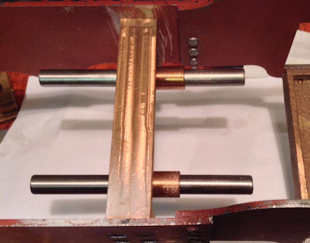
3rd October 2014 Just a short while in the workshop allowed me to cut off, clean up the ends and use wet and dry to make a good sliding fit of the second valve gear rod. |
 |
| 3rd
October 2014 the parts will be machined as the drawing shows |
 |
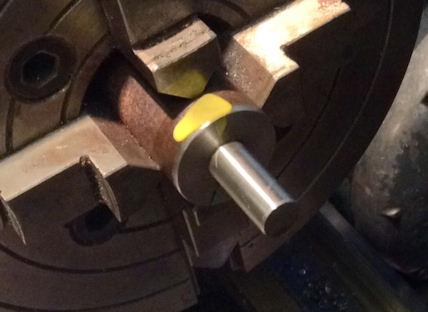
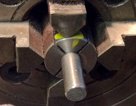
Early October 2014 I was recommended by a friend to :- Set your 3/8" rod in the 4 jaw to run true. Now unwind one jaw and put a 3/32" drill between the jaw and your rod and do the jaw up lightly to grip it. Now knock the drill out and do the opposite jaw up so that it pushes the rod over to meet the first jaw. Then do the other two jaws up carefully so that they grip the rod without offsetting its position. With all 4 jaws done up firmly, the rod is now offset 3/32" from the centre line which is what you want. Turn the first 1/6" or so of the bar down to 3/16" diameter and look to see if it is as you want it. If it is right, turn the rest of it, if it is not, then adjust the jaws as necessary. Do the 2BA end first, just hold the bar in a 4 jaw chuck offset by the desired amount and face the end but stop leaving about 3/16" diameter and check that the offset is where you want it. If it is not then adjust the jaws to correct it and face again. When you are happy with the offset, which is not critical, turn down the length required and put the thread on it. 7th October 2014 With a collet made but with only one slit, as shown opposite, when the thread was put on the piece turned slightly. So for the next one additional saw cuts were made in the collet so the each jaw of 4 jaw chuck applied pressure equally the the work piece. |
 The
picture shows the first version of the collet which only had a
saw cut right through on side. This did not grip the bar well
when it came to threading it.
 The
second version this time the additional saw cuts went to
about 5mm from the far end. This properly gripped the bar.
|
| 9th
October 2014 The photo shown both the bar threaded off set and now ready for the next operation as described below. |
 |
| 20th March 2017 A return to machining the Valve and their cross drive piece resulted in fining out that there was not sufficient material to complete the job in fact the valve now has a hole in it. The valves will be confined to the waste bin and new ones made from stock I have. I now also understand that it is steam pressure that holds the valves on the port faces. For this reason, I will need to limit how far off the face the valve will fall when not under pressure. The valve needs to only be able to lift about 15 thou before it touches the steam chest cover. |
 |
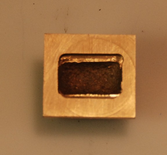
| 21 to 25th March
2017 After pondering what to do I decided to cut of two pieces of square steel bar and machine the necessary new valves. The top photo show the work with just the main block machined partially. The lower photo shows the slide valves with most of the milling completed, with the sadly broken 5/32" slot drill. Not yet shown is the relief on the underside of the valve to take the exhaust steam to the chimney. |
  |
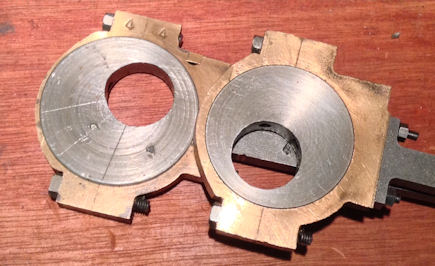
| 31st March 2017 Here I am showing the progress on both of the valves. They have now been brought to size on the width so that they easily slide sideways over the ports, relief has been made to account for the brass fitting at the rear end and also adjacent to the steam entry point so that it can freely move around the steam chest. On the valve face at the front you can see the relief machining to take the exhaust steam to the chimney. |
 |
31st March 2017 You can more clearly see the machining to relieve around the brass fitting at the rear end and also adjacent to the steam entry point. Final fettling is required and the milling of the slot to take the driving threaded part which moves the valve over the ports, Note the valve has been positions to face the camera hence the different view than in the rear steam chest above. Later the cross slot was machined to take the drive piece to action the slide valves. |
 |
| 12th June 2017
Work started on locating the position for the threaded
hole for the valve drive piece.
First I located the drill the same size as the hole at the entrance to the steam chest and by pressing the valve with cross drive piece in place was able to make a small mark. This was then drilled through with the piece held in a vice and tapped M4. The driving rod was threaded M4 and the two piece tried for fit. Oh dear there was too much movement allowing the valve to move of the ports. So a second piece was tried but this time the mark made by the drill was just used as an indication of position and a punch mark made just above the drill mark. This
proved to be successful and a little filling of the drive
piece so that it gave
the required clearance so that the valve needs to only be able
to lift about 15 thou before it touches the steam chest cover
or underside of the drive.
|
 |
| 26th June 2017 So this is the current look at the bench as I again try to get started to work on the loco. I had read in 1model Engineer of the 9th June of an idea to cut two "Octagonal pieces of ply wood which can then be bolted to the buffer beams of the engine and provide a steady working environment to access the under side or top side of the engine. The author of the pieces said it was not his original idea but that he too had read it some where. |
 |
| 26th June 2017 From the plans I measured the height from rail base to top of chimney and added 25mm. Two squares were then drawn and cut out and then the corners cut off to make the eight sides pieces. The first piece was then used to as a template for the second so that they were identical. The idea performs the job very well and could easily be made more stanble by removing the piece of track and attaching a temporary setion of wood bolted to the side meeting the work bench. |
 |
| 3rd July 2017 I quartered the wheel in the lathe and used 603 adhesive initially but eventually the wheels will also be pinned when it has been proved the the quartering is successful. |
 |
| 7th July 2017 So with the wheel fitted it is time to consider the other parts of the valve gear. A slitting saw will cut the two round bars with the offset threads and advice from a friend is that for "slitting saw speeds" it depends on what material you are cutting. Every material has an ideal surface cutting speed, fast for brass, slow for iron, etc. This is the speed between the material and the cutting edge of the cutter so the bigger the diameter of the cutter, the slower the rpm needs to be. The easiest way to visualise it is to think of a round bar of the material you are cutting being the diameter of the cutter. Now assess what speed you would spin that bar if you were turning it in the lathe with a HSS tool bit and that is the speed the saw needs to rotate. From other source ( as given in the book "The Amateur's Lathe by LH Sparey ) the Rate in feet per minute for Silver steel using a HSS tool is about 50. This can be converted to RPM by the formula Cutting Speed / a quarter of the work diameter = R.P.M. As my saw is 3" Cutting speed = 50 1/4 of the diameter of the saw is about 0.8" so 50 / 0.8 = RPM = about 62 RPM So I need to set up the lathe to give me that speed of less for safety !! |
 |
| 4th
September 2017 I decided to install a system which converts single phase household supply to three phase to drive a three phase motor. This had been delivered to me a few days before from Power Capacitors http://www.powercaps.co.uk This will give me a variable speed drive at full torque. The motor was up rated from .75 HP to 1 HP, a Jaguar CUB Inverter 5A and a remote Control Station with cables to connect between each unit. The installation was completed over a two day period of 4 hours in total and the old motor keeped in case of any failure of the new system. |
|
| 9th September 2017 After a day on the Kent and East Sussex Railway I decided to drill the valve rod. I had prepared a similar sized bar and used the lathe to drill a hole in the centre and both ends were faced off. |
 |
| The part to be
drill was placed in the drilling vice and the centreing piece
placed on top. I had calculated the location and measured down from the threaded end to the outside of the drilling and carefully tightened the vice and drill through. |
 |
In October 2014 I received this advice Hold the bar end to be slotted in the tool post at centre height with the offset at the other end offset horizontally. Now use the cross slide to move the bar onto a slitting saw held on a spindle in the chuck until the slot is as deep and as wide as you want it. Regarding the use of a slitting cutter just use the one cutter and take as many cuts as you need by moving the saddle up and down until the slot is the width you need. Once it is the right width, move the saddle from side to side with the cutter at full depth. This will clear any steps at the bottom of the slot. It is OK to move a slitting saw sideways while it is cutting so long as the cut is less than the depth of the teeth on the cutter. You need to run the cutter fairly slowly, just as if you were turning a steel bar the diameter of the cutter, and use plenty of coolant. You can never have too much coolant. |
 |
| 10th September 2017 Today I tried my slitting saw for the first time and all went well. Careful setting up was essential! So first off I turned a bar to the diameter of the hole drilled yesterday and then using my quick change tool post I made adjustments so that the bar when all tightened down could slide from the drilled hole. To double check squareness I then moved the bar against the chuck and all checked out perfectly. |
 |
| I used a 1/8"
slitting saw at a speed of about 70 RPM and gently
brought it in to nearly touching the bar and double checked
that is was in the centre. Very light cuts were taken until the depth had been achieved. You can see that I had to use careful packing both behind the bar and also above the bar so that the fixings in the quick change tool post did not damage the bar. |
 |
Another view of the set up ... The total time to make the cuts in the two bars was 2 hours using plenty of coolant! |
 |
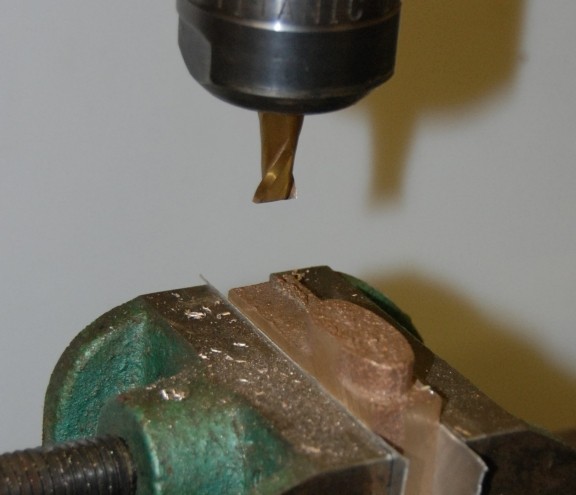
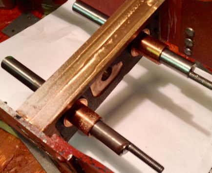
| 14th September 2017 I made up all the necessary pins with cross drilled holes for the valve gear. Having the variable speed drive made machining to size and parting off an fun task as no belt changes ! To drill the cross holes I used the idea seen on YouTube where a piece of metal is turned the same size as the piece to be cross drill this is shown in the photograph, centred then drilled the size of the hole in this case 1.5mm. The piece to be drilled was then held in a machine vice the additional guide piece set on top and all tightened up and then the cross drill made. This method ensures that the cross hole in in the centre. |
 |
| 17th
September 2017 The valve gear linkage arms were cleared of swarf from the milling and are now to size. No photo as nothing to show for the change ! |
|
| 5th October 2017 Errors in parts found and remade to complete the actuating parts of the valve gear so far made. |
 |
| 7th October 2017 The support for the cross shaft is a casting which started out as the two brackets all in one. This did made machining easier and it is a simple milling operation. As the critical part is the landing of the bracket to the side frames and the reamed hole I made certain that both these operations were carried out with the part in the machine vice and then removed. |
 |
| Not the best photo as the
light level was rather low! However the bracket part sits well in its location and now I need to sort out it final position and the drill the necessary holes from those in the frames. |
 |
| Both brackets in place and the cross shaft fits well ! |  |