The Diary of the Building of a 5" gauge Stirling Single |
|
|
|
|
|
|
|
Crosshead |
|
| 1st October
2013
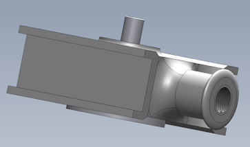
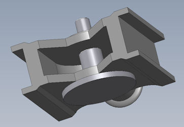
To have a good idea of the Crosshead I asked a friend who knows someone good with 3D cad to draw up the item. The images are screen grabs of the item as rotated by a program called Solidworks eDrawings which was free to down load from the web. This now helps me to understand the engineering drawing that I bought so many many years ago. |
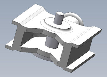   |
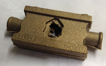
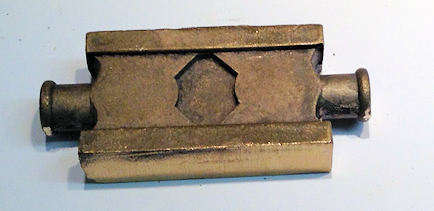
| This shows the casting as made. |
 |
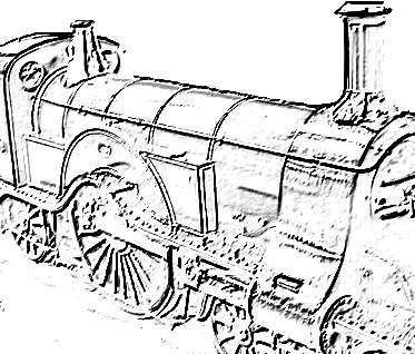
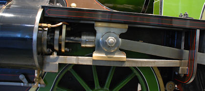
| When I visited the NRM a few
years ago I took this photos of the cross head on No.1.
One can clearly see that the nut fixing the gudgeon pin is on the outside with a split pin securing it and a washer like protuberance beneath.
|
|
| 10th November 2013
After consultation with a friend these are the ideas I learned to follow to achieve an accurately machined Cross head. Note when any machining is carried out protection pieces of material will be used to reduce damage to the casting. The casting was machined on the outside faces in one piece so that it is dead to width and equal about a centre line. This was then marked out using the machined faces as datum through the middle of each end vertically which could then accommodate measurements. This line to be scribed using a vertical block to which the casting can be fixed and the suitable scribed. |
 |
| Next the top and bottom need to be brought dead to size so a centre line will need to be scribed using the protrusions on the ends of the castings as a guide so that the centre line is in the centre of these protrusions. | This is where the trouble
started this time round. When all the machining was completed
the gap between the slide bar was great. The problem was some
how it was all off centre but not by a little bit but several
mm. A new casting has been ordered and I have time to consider
where my marking out went wrong and start all over again. It did
prove that my machine vice is properly set up and holds items
very well.
|
| The centre line marking was
fine but when marking out not only should I have had the centre
line but also a line on the side to indicate where the outside
cut will be down to on the top and the bottom. This would have
immediately indicated that I was not cutting correctly and I
could have taken some remedial action.
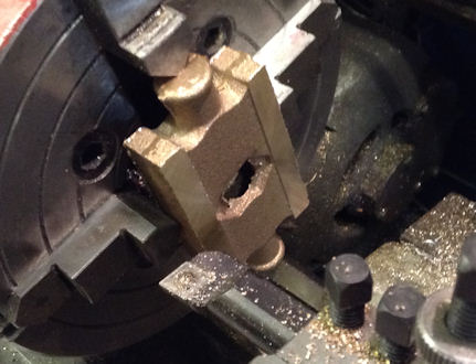
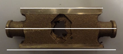
As it is one side is almost exactly right with the error solely on the other side. When the new casting arrives it marking will be done with many move witness lines so that errors become apparent way before it is too late. Also the depth of the grove for the slide bar to be in on the side where it is correct to the outside measurement is only 1.5mm and it should have been 3.174mm. So there is an error of 1.675mm which when added to the other side rectifies the error. The additional marking out lines would have stopped that error as the casting could have been lined up in the vice and double checked. The photo shows the errors rather well. I have added the lines for making out and this makes the error even more obvious. a lesson learned. |
 |
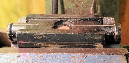
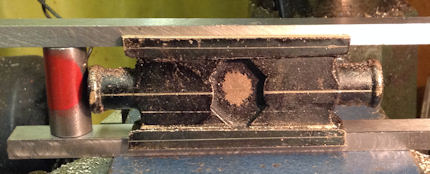
| 11th November 2013
The new casting arrived in the post this morning. I looks slightly different from the original as the centre will have to be machined out where as the original had a void. The centre line was marked using Spectrum Blue both along it length and also on the top edge so that when put in the vice to mill the laser pointer made sure that it was parallel to the bed of the mill. |
|
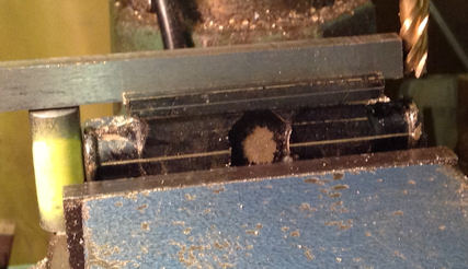
| So the first operation was to machine the sides to width which when completed the tops were similarly machined checking that the casting was set correctly in the vice using the laser on the centre line. The photo show that the cut is going well and the cut line at the max depth if visible. | 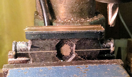 |
| Progress we made and both the top and bottom were machined and all staying to size with no error. | 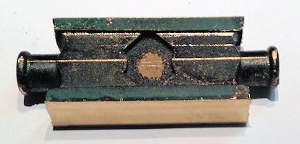 |
| With all the machining completed on sides and top and bottom the marking out for the grove to be cut in the top and bottom was made with a witness line to ensure the cut does stay central. | 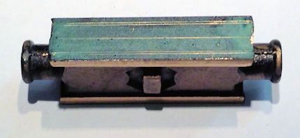 |
| 15th November 2013
Next the casting need to be placed in a vice on a stand off parallel so that the vice grips the casting well. I know the vice jaw are accurate from the past milling so setting up was easier. However I had decided to make up to distance piece turned to exactly the right height from the flat to the bottom of the groove and this is the round p[art painted yellow. The photo shows that the depth of the groove is nearing completion. |
 |
| In this photo you can see how much more of a cut needs to be made when looking where the cutter is and the top of the distance checker. | 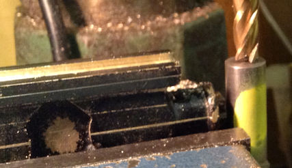 |
| In this photo you can see that a piece of cigarette paper has been used to check the "touch" "no touch" on the distance setter. | 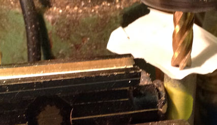 |
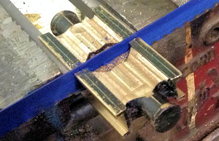
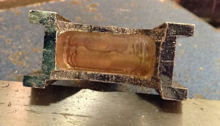
| In this photo you can see the final cut has been made and it brings the depth to size and the sides has been widen so the that the groove is the right size equally about the centre line to both top and bottom. | 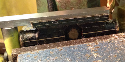 |
| Here the cross head stand
between two slide bars with the machined check spacer in place
indicating a satisfactory fit.
The time use to make up the test distance pieces at the start certainly reduced the measuring and I think also greatly reduced the likely hood of error. |
 |
| 16th November 2013
The casting then machined on the front and back faces to clean up the the casting sand marks and then was cut in half in half so that each part will be machined individually. |
 |
| In this photo the casting is having the end part machined away and this was finished off with a file. | 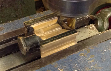 |
| I had to work out how to know the deep the 3mm milling cutter was going so I set up the laser pointer so that when the milling cutter entered the casting the depth was indicated as a dot on the outside of the casting where the marking out had been scribed. | 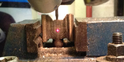 |
| The use of this method to
determine the location of the cutting point was successful as is
shown in the photo. Any small burrs can be removed with a file
or similar if found necessary.
17th November 2013 Today the second Cross Head was completed regarding the milling out. |
 |
| |
|
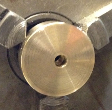
| Move the casting into a 4 jaw chuck and clean up the ends of the casting behind the protruding part so that shortly it can be used as a datum to check the casting is accurately located in the centre of the 4 jaw chuck. Use this cleaned up surface to bring the casting dead to running true by moving the chuck round by made and using the corners as the witness as to trueness. DO NOT take a cut just the location is all we are using for if all the other dimensions are correct the 4 corners to be set at equal distance from the centre and then the casting will run true. The machine up the casting to a nice finish before boring and reaming for the piston shaft. | |
| When drilling for the taper pin it should go through about 1/8" but take it carefully with the drill the size of the small end of the pin and if not sufficiently only advance a very small amount as to the progress of the pin needs to be check as small changes will move the pin well forward. | |
| 12th October
2014.
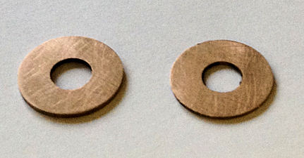
I decided to have a go at cutting the 0.8mm washers which will be needed inside the cross head. two per side are required. The photo shows the first two made without mishap and using a 3mm parting tool so in fact more materials was machined away than used ! Sadly now in 2017 I cannot find the parts BUT I need four so I will remake all together !!! !!!! |
 |
| 15th October
2014.
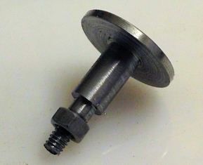
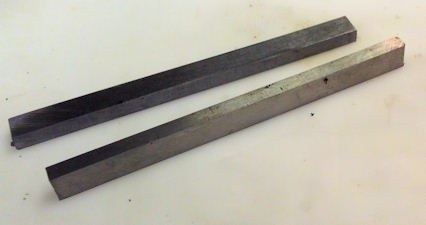
A start was made on the gudgeon pins and this is the first one. The parting off went well resulting in little loss of stock |
 |
| Also on the 15th October
2014.
Next I started to tackle the long job of cutting the Slide Bars for the Cross head. This is in 1/4" gauge plate which I had not used previously and found it very tough to cut through on the band saw but after 90 minutes one was cut and finished and two more followed the last one being cut more accurately from the remaining gauge plate and only needed a single pass of the mill to bring to size. |
 |
| 7th October
2014.
It has been suggested to me that:- The piston should be turned 25 thou oversize and face it to length. Drill half way through the piston with a 1/4" drill and the rest of the way at 7/32" and tap it 1/4" x 40. Set the rod up in a 4 jaw chuck using a DTI to ensure it is running dead true with 1" of rod sticking out of the chuck and centre drill the end, to take a revolving centre in another operation shortly, and thread it 1/4 x 40 for 1/4" of its length. Now screw the piston onto the rod in the chuck as tight as you can (with Loctite on the thread if you wish) so that the plain hole runs onto the plain 1/4" rod, tightening it with grips on the piston until it will go no more. With a live centre in the end of the rod to support it, turn the piston to the size you want and put the ring grooves in with a parting tool making the grooves about 1/8" deep and only as wide as the parting tool. When done, slide the rod into the chuck until the piston is against the jaws and face off any rod that may project from the piston when it was screwed on. Leave the overall length of the piston rod at least 1/2" longer at this stage and it can be cut to length when the crosshead and con rod are in place. With this in mind it is the way I shall proceed. |
|
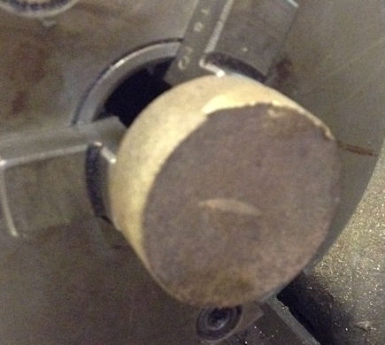
| 10th October
2014.
The photo shows the raw casting of the piston. |
 |
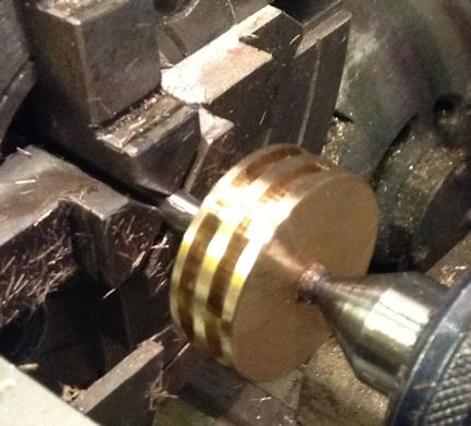
| The photo shows the piston machined as near to the lathe head stock as practical. | 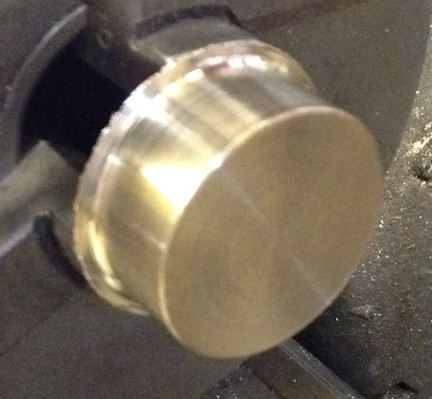 |
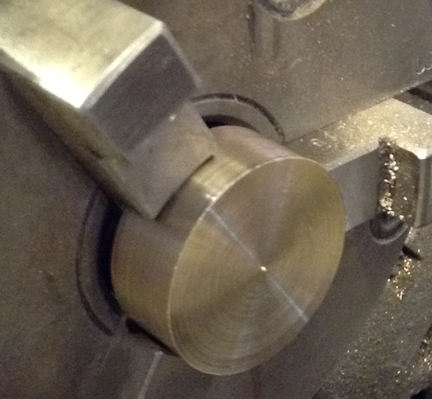
| Here the photo shows the
piston reversed and the machining completed and to length.
The slight pip indicates that the tool was a fraction below the centre line that has been corrected. |
 |
|
Without removing the piston from the lathe the centre hole was drill half way through at 1/4" and then the remainder 7/32" and tapped 1/4" x 40 ME |
 |
| First the piston rod was
centred in the 4 jaw chuck using the DTI.
The piston was fitted using 603 adhesive and left overnight. The piston ring groves were then machined in using a well ground parting tool. All that remains is to do the final facing off. All the recommended procedures were followed and a good result achieved. |
 |
| 11th October
2014.
The second pistons was machined and when both were tried in their cylinders the fit was good. |
 |
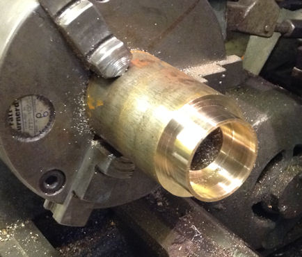
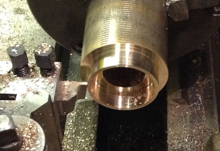
| 24th October 2014.
Work started on the piston rings. First a suitable parting off tool was ground to that the amount of material cut away was 1.5mm so less than was being cut off for the ring of 2.7mm The photo shows the phosphor bronze cored material bored to the correct internal diameter to allow a small gap before bottoming out on the groove in the piston and the correct outside diameter to allow for a cut to be made with a hack saw. |
 |
| The parting off tool was
ground so that there was very little overhang greater than
necessary to allow for the thickness of the ring.
The tool had been aligned with the faced off front of the material and the cross slide locked in position and wound in on the dial 2.7mm. |
 |
| Two of the four rings parted off and ready to be cut and as necessary filed so that the ring is a fit in the bore of the cylinder without the end binding. | 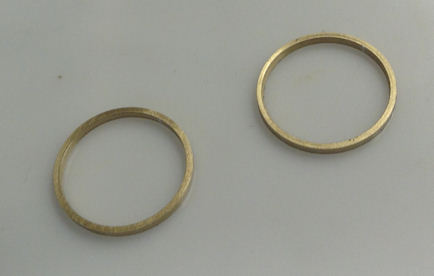 |
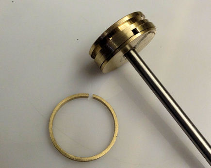
| 25th October 2014.
Here you can see in the lower part of the picture the saw cut. A trial fit of the ring into the cylinder showed that the OD was a little too big so and the gap has been widened a little so that the ring when compressed is a good fit into the bore of the cylinder without binding. In the upper part the piston has had one ring fitted with just the second one to fit before it is ready to fit into the cylinder. |
 |
| The piston is now fitted into the cylinder in which is slides well. | 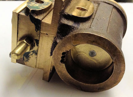 |
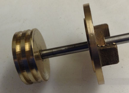
| 8th
March 2017 OK so it has been a long time but with a revamped workshop I am getting under-way again with the build of my Stirling Single. Due to an error being found it was decided to make the piston rod from 5/16" bar in place of the 1/4" so the original piston rod was removed from the piston, 5/16" bar cut and machined to length in preparation for turning one end down to thread 1/4" x 40 to fit the piston and the other end to be threaded 5/16" x 40 to fit the amended cross head. Later in the early evening the 5/16" was machined down to 1/4" and then the 1/4" x 40 thread was applied to both piston rods and the 5/16" x 40 applied to the other ends. One of the rear cylinder caps was reamed out to 5/16". The photo shows all the amendments assembled. |
 |
| 12th March 2017 I had to true up the vice to ensure the tapping holes were drill square. I used two set squares and shone a torch from behind, when I could see no light I knew it was true. |
 |
| This is how I used the
vice to hold the cylinder for drilling the tapping hole. This is the second cylinder and I had to also today prepare the cross head bars by milling to fit, drilling and tapping to tap 6BA bolts, align the end cap to the correct position ready for the drilling as shown in this picture. |
 |
| With the holes drill
the tapping could take place. A few holes first and then all the
others. I used a button which I had made to holed the tap at
right angles to the face and thus had a true hole at right angle
to the face of the cylinder. |
 |
| The the original
tapping hole size had to be opened out as the End Cap had been
used to locate the tapping hole. |
 |
13th March 2017 This photo shows that all the bolts are in position. the bolts has to be shortened by about 4mm from the length I had bought. |
 |
| The so many bolts to
shorten to the same length I drill this 5/16" piece of steel,
drilled and tapped it 7BA and cut all the necessary bolts to
length |
 |
| The drilling and tapping nearly completed just two locations remain. |  |
| 14th March 2017 Much of the day spent with a friend helping to clear my workshop loft of stored items from about 30 years, and installing some timber to support a ring main cable. However I did find the previous Gudgeon pin and made the second one. |
  |
| 15th March 2017 The washers for the Gudgeon pins as now made and fit the Gudgeon pins ! |
 |
| 28th October 2017 I decided to try to make the pistons driven by the wheels as my goal. So after assessing where I had reached I had to ream out the second rear end cap. Then work was done to make the cross slides fit and the piston rod had to be further threaded 5/16" x 40 by ten turns of a 1/4". The ends of the guide bars has to be milled to allow the connecting rod to have sufficient room to allow the wheel to turn when connected to the connecting rod. After a total of 51/2 hours work the result is as shown opposite. The wheel do turn by very stiffly but that will ease with running in. A very pleasing result from a days work. |
 |
| 29th October 2017 With the wheels going round it was time to drill and fit the parts which hold the slide bars. Using the holes in the support I drilled with a hand drill the holes for the 6BA bolts and then thought there must be an easier way to drill the holes. |
 |
| The loco was already
mounted on the Octagonal pieces of wood, an idea which came from
an engineering magazine, and I added a brace which can be seen
attached to the far piece of timber to prevent rotation of the
loco in this rather unbalanced position and held in place by two
M5 bolts and nuts.. Having "Brain Stormed" with my son in law who is an engineer we came up with a simple way to make the drilling easier. Until this photo was taken the loco was actually upside down but is was rotated through 90 degrees to the position as seen. Now with the use of my old drill stand and drill which are about 40 year old it not more, the drill of the holes was made much easier as I had much better control of the drill and all the holes were drill and the item bolted down. With both parts now bolted down the wheel still turn but with much effort! Using the drill stand will make it much easier to drill other holes in various places. |
 |
| 30th October 2017 Today the guide rods were finally fixed in position which required more milling of the one top of the photo, which is actually the bottom guide, and then drilling a tapping hole for 6BA and then tapping, cutting a 6BA bolt to length and fitting. Whilst the guide rods were out the piston position was adjusted on the piston rod so the there is equal distance at each end. In fact only one had to be altered by about 1mm ! All this work took about 3 hours as it is especially careful work as I have achieved this without any shim packing ! |
 |
| 1st November 2017 All day spent on the linkage so not much to show but it does all move. A provisional setting of the valve gear but this will need to be checked when the steam chest are fitted. I have found out the the lifting arm linkage to the expansion link to too short according to the plan so new ones will need to be made. |
 |
| 2nd November 2017 The photo show the pinning of the lifting rod to the levers. A 1/16" drill holes was made but sadly in the second hole the drill broke and it was recovered and the two levers pinned to the lifting rod. |
 |
| A close up of the drilling set up. |  |
The remainder of the
linkage through to the valve actuation. |
 |
| 3rd November 2017 I found that the intended location of the revering lever fouled the boiler so decided after a trial mounting a little further back and cutting out part of the stand the it needed to be mounted externally to the frames. |
 |
4th November 2017 |
 |
| 5th November 2017 The fettling mentioned above to ease a jambing part was achieved with my hand held linisher, recently purchased. Time to day achieved very little progress but will lead to being able to use compressed air to turn then wheels. The supply fittings were made to link to the air compressor and several of the gaskets made and fitted. However a simple test showed that the air was lifting the valve on the left hand side allowing the pressure to escape without entering the cylinders. |
|
| 6th November 2017 Finally all the problems sorted out and the first run on air achieved. The valves were improved by the use of wet and dry to make a good seal to the face of the cylinder. The timing reset on the forward eccentrics. The binding of one of the valve drive spindles was corrected by an amount of filing to allow the parts to run without touching / binding. A large amount of oil is being used both on the parts and in the air line to ensure everything is well lubricated. |
 |
| 20th
November 2017 The connection rod was removed and oil ways drilled to the front and rear bearings and then replaced on the loco. |
|
| 25th November 2017 The second connecting rod was removed and oil ways drilled to the front and rear bearings and then replaced on the loco and a new locking piece made to complete the bearing locking system. |
|
| 3rd December 2017 This should all have been done whilst the cylinder was off the engine so today a three hour job to take of the steam chest cover and released the cylinder from the chassis and remove both ends caps them mount the cylinder in the milling machine. A flat was machined on the underside at each end to give a surface for the drain cocks to sit down to. The cylinder was then drilled 5.5 mm as the tapping drill for 1/4" x 40 thread and then tapped. Everything was then reassembly and given a test run on air using fingers to stop the air leaving through the drain cock holes ! Later in the evening two bungs were made up and put in place until I have made the Automatic Drain Cocks. 4th December 2017 The other cylinder was similarly removed, drilled, and tapped and replaced on the chassis. A friend lent me a socket set with a UJ attachment which enable me to much more quickly remove the bolts holing the steam chest cover. In fact all was completed in about 90 minutes ! Some more "Running in" was carried out as things seemed to have stiffened up a bit, but no obvious binding ! |
 |