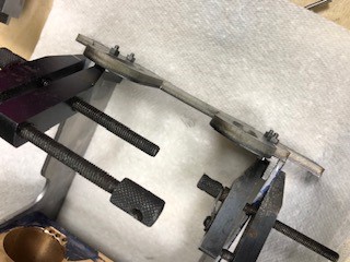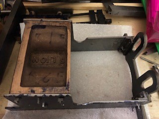
The first side with the try square was super glued earlier and the pilot holes spotted through.
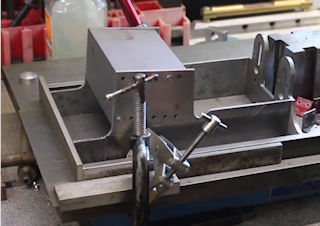
I had previously made up a simple flat surface on a piece of glass in a wooden frames. The first side was set and spot drilled so now the second side had to be carefully aligned in two directions. The glass ensured that the bottom aligned with the bottom of the cylinder and I clamped a try square so that I could align the front. After both parts has been cleaned up "super glue" was applied and slowed to set.
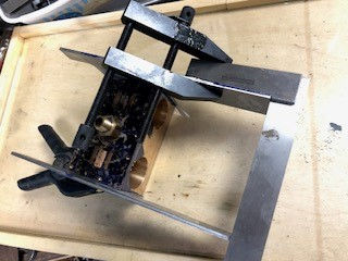
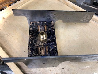
All bolted up and remained square !!!
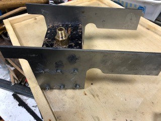
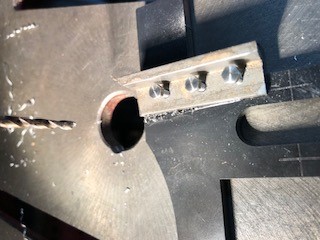
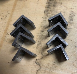
Today I started the drill of the angle pieces which were cut previously to connect the various parts of the frame work together. one side will be riveted and the other bolted. The same pilot hole drill may be used after I have checked the size for the 4BA tapping hole.
The first angle was set up in the vice having been marked out ( but this is a mock up as I had already drilled the first piece ) and centre punched.
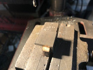
The reverse side will need to be cleaned up to remove burrs.
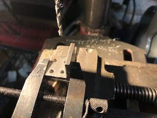
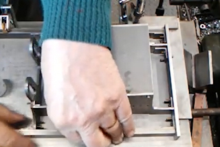
The remaining 32 holes were drilled at a size for tapping 4BA and then as necessary they can be opened out to 4BA clearance.
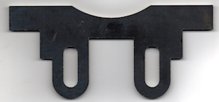
I have had the motion plate laser cur which is saving me a lot of drilling and filing. The straight line has to have a 5 degree angle applied. So I need to set the motion plate up on my angle plate and check that the two flat piece are correctly aligned so that the same amount is taken off both side to maintain accuracy and then match the angle on the radius in the centre.
To attach the motion plate to the cylinder two pieces of angle iron are require which I will machine from steel slightly larger.
I have watched the YouTube https://youtu.be/M2_TdwE2MRE which is a great help.
I think something is telling me today is not a good day for engineering, one slot cutter broken, one shift of angle plate move, so think about what went wrong and start again tomorrow with a clear head !!!.
So what went wrong.
1. I did not use a piece of paper under the angle block which is used to prevent slippage
2. the cutter was old and thus did not cut cleanly.
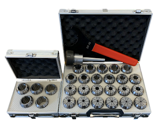
With the failure to day I decided to treat myself to a new ER40 collet chuck Morse taper no.3 and a set of slot drill. The photo is from RDG tools page
https://www.rdgtools.co.uk/
My original one was bought way back in about 1975 so it has done well but needed threaded tool which are getting more difficult to source.
Another day and another start. This time I decided to attach with super glue the angle before cutting and then then drilling for 6BA bolts and as necessary cut away what is not needed.

