Carburettor
5th November 2010
I have been looking in detail at the
drawings for the
Carburettor and I have written an email seeking confirmation that
may be the drawings have been altered as I cannot work out the parts fit
!!
Well the reply is "The holes can be
concentric or as per drawing as theirs work as per drawing."
I will be making mine as per the story
below. |
| 7th November
2010
I
am considering making the Jet tube with integral non return valve. The initial
drawing is shown.
However the small sized proved impossible
for me to make so the M3 was changed to M4 which did proved difficult but
possible!
The non return valve works when I blew
into it so I do think that it is a practical solution. |
 |
Here are the first parts of the carburettor
made. |
 |
| 8th November 2010
The jet screw with the knurled edge has
now been made and length adjusted to bottom "just" on the fine drilled hole
through the jet tube.
Also in the picture are the two reamers
for the 10Deg and 20deg entry / exit of the carburettor. They have yet to
be hardened and tempered. |
 |
| 14th November
2010
I have been giving thought as to how
to make the Carburettor
body. The Throttle has a hole in it that
needs to align as far as I can tell with the hole through the main body.
The only way of ensuring that, for me at least, is to machine up the main
body from round bar but leave the ends unfinished and the sane size so that
it can be re-held for further drill and tapering, drill through with 4.75mm
drill and then mill the centre section to the rectangular
shape.
Then with the part still set for the
cut across the top flat surface slot drill down the 12.7mm. As I do not have
a 9.5 mill I will have to do it 10mm and then make the throttle a slightly
size larger.
Then insert the throttle part and drill
through the 4.75mm hole which will already be there and all will align.
A modified drawing is shown below ...
without the entry and exit cones. |
 |
| By making an engineering
drawing, as below, it becomes apparent that to make the carburettor body
the od of the main parts needs to be 22.63mm so that this full encloses the
16mm rectangle.
The reduced diameter to 11mm, as seen
above, can be machined in place leaving the ends to be reduced later.
This diameter of 22.63mm also allows
for the 10mm part which is to be threaded M4 as it comes within the od of
22.63mm.
The part threaded M4 is the full width
of the initial round bar for ease of manufacture so includes the darker orange
parts. |
 |
| A piece of brass stock has been machined
to OD and had reduced areas made to an OD of 13mm rather than 11mm. |
 |
| The piece has now be made true to
length and awaits the centre piece to be squared. |
 |
| Here is the set up in the mill for
the first cut of the squaring. |
 |
| Here is the set up the make the second
cut at right angles to the first cut |
 |
| Here is the set up for the mill cut
of 10mm to a depth of 12.7mm. |
 |
| The main body partially
finished. |
 |
| Here are the parts to the carburettor
made so far. |
 |
| The centre insert which forms part
of the throttle was machined as a nice fit in the hole and was made to allow
0.3mm above the face of the body so that it will be pushed down upon
by the middle screw spring on the arm.
The cross drill was done by inserting
the piece in the centre hole, clamping it with a tool maker's clamp, and
then drilling through the existing hole in the body. The piece was then returned
to the lathe to drill a suitable sized hole through the centre to clear the
M4 shaft.
This was all satisfactorily
completed. |
 |
| A holding piece was then made up
similar to that used for the gears but much longer and the body pressed inside
as when the holding piece was cut to contracted in size.
Both ends were then reamed using the
taper reamers which had be hardened and tempered. They did not work as well
as expected but did the job.
The entry end was then opened out by
the use of a small boring bar and all made good by the use of a scraper and
wet and dry.
The instructions call for a 3/4" x 26
tpi but as I only have a 5/8" x 26 the end was machined to that size and
will be threaded in due course.
The other end that mates with the engine
needs a 1/4" BSP thread and the OD for that is 13.1mm so the end will be
reduced prior to threading.
The photo shows some of the other small
parts of the carburettor |
 |
| 15th November 2010
Here is the carburettor as far as I have
made it today.
|
 |
| Then just before supper the choke
was made so the carb is complete except for a foam air filter which I have
ordered in sheet form. |
 |
| 23rd November 2010
The new carb was designed and made all
but the non return valve. The design below was contrived from information
from my friends John and Mike and looking at picture of carb / mixers on
the web, checking out the Bernoulli's principle that if air flow through
a restriction then is pressure lowers and created a vacuum which will draw
fuel into the air flow and of course Westbury's book " Model
petrol Engines" |
 |
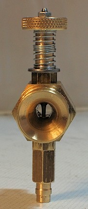
| 24th November 2010
The final part of the carb was made and
the engine tested again. The inlet port had to be reground as it was found
to be leaking - nothing to do with the carb as all..
In the picture you can see a nice clear
passage and the needle goes into the needle jet and the surface of the jet
is level with the bottom of the port.
The entry is actually belled out a little
more than shown in the diagram so that the entry is nice and smooth.
This time I made the unit from HEX stock
which meant that I did not have to face of top and bottom and the sides all
saving time.
A steel needle was made and the point
made to descend into the inlet as shown in the diagram. |
 |
|
|