Timing
|
|
| 17th October 2010
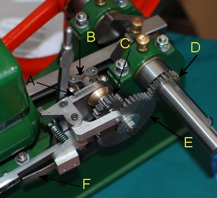
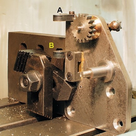
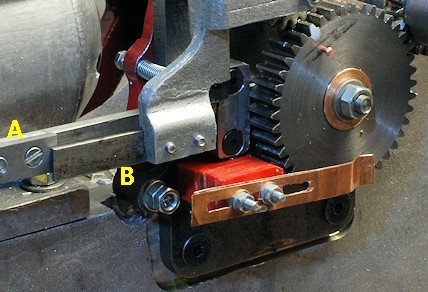
Whilst at the Midland Model Engineering
Exhibition I was able to take this photo.
-
A. Timing Plate
-
B. The Governor
-
C. The Governor Gear
-
D. The Crank Gear
-
E. The Timing gear
-
F. Striker Strip
The location of the timing plate is determine
by the correct registration between parts D and E and the other parts are
all associated with the Timing plate. |
 |
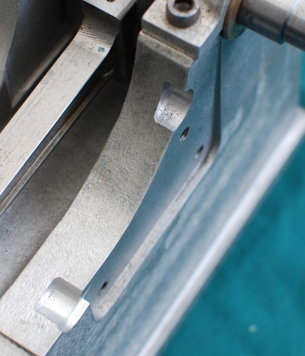
| Again a photo take at the show indicate
that machining has to be carried out on the side of the lower casting to
allow the Timing Plate to lay at Right angles to the main shaft and thus
allow the gears to properly engage. |
 |
| 18th October 2010
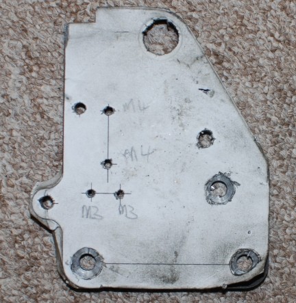
At the Midland Model Engineering Exhibition
I was able to purchase from the casting supplier a blank for the timing plate.
I had thought that I would obtain one with hole already drilled but sadly
this one came unfinished.
I produced a drill overlay of the part
from the dimensions given in the plans.
The place at which to drill the various
holes were then centre punched and drilled.
The photos shows the part with holes
drilled to size as clearance holes of tapping holes. There are two holes
to be tapped M3 and two holes to be tapped M4
The large hole at the top has to be 16mm
diameter but I neither have a drill that size nor a reamer so the part was
put into a 4 jaw chuck and fine cuts taken to bore it out to size.
Eventually the paper cover will be removed
and the part painted. |
 |
| 5th November 2010
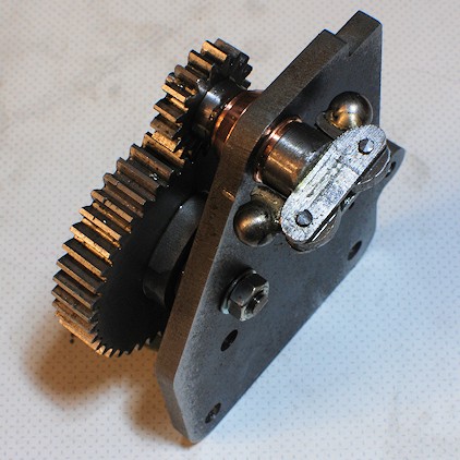
Parts are assembled onto the timing plate.
The governor is secured by a M3 grub screw which is on the under side of
the part. All are free to rotate. |
 |
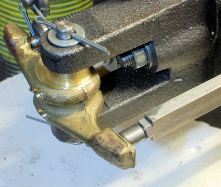
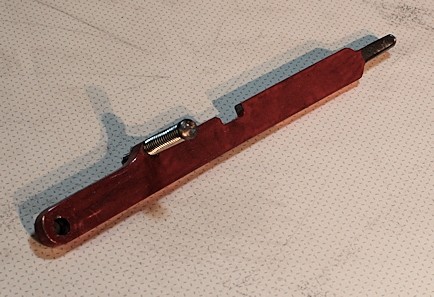
| 16th November 2010
The end of the push rod with the adjuster
made. The spring on the exhaust valve has to be strengthened .. It may still
need to be changed !!!! |
 |
| The insulating base of the timing
arrangement was made from plasticard laminated together and then drill according
to instructions. The timing strip is two pieces of bronze strip soldered
together as a single piece was too flexible.
The timing stud is at present a 1/16"
copper rivet but that may be changed to a hall effect timing system eventually.
The two lines draw in pencil were to give a guide as to the centre location
each side of the studs holding the strip.
A washer and nut has to go on the end
of the timing gear shaft. |
 |
| 17th November 2010
The whole of the timing plate had to
be removed so that the governor pieces could be fitted.
Part A in the photo is the Speed lever
Stop. This had to be drill and then the top of the timing plate tapped M3.
Also a hole to hole the Striker pivot pin was drilled.
Then part B had to be fabricated and
an M4 tapped hole put in the back so that it could be secured with a counter
sunk allen bolt.
|
 |
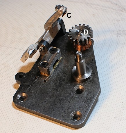
| The striker arm had several holes
to be drill and tapped and the main pivot hole was aligned and drilled.
The contact adjuster part C in the photo
was made and the governor push rod, D, was filed to length. |
 |
| The speed lever and associated parts
was made this evening. |
 |
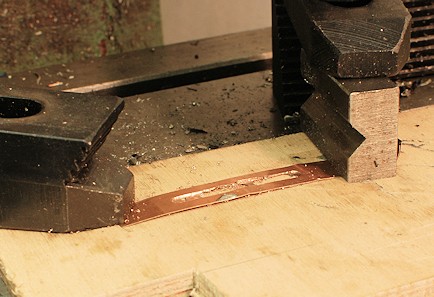
| 18th november 2010
Milling the timing strip so that it can
accommodate advance and retard. |
 |
| The striker plate A and striker strip
B made and in position. Also in the photo the improved timing strip.. |
 |
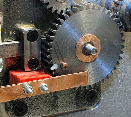
| The engine with all the parts on
the timing plate now made and re-assembled. some easing of the main lower
casting and the upper casting was needed to allow for the altered design
of the speed arm which is painted red. |
 |
|
|
|
|


 TO BE CONTINUED