| 13th
October 2010
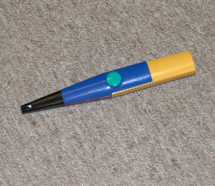
The idea was passed to me by a
fellow model engineer that it might be
worth trying an electronic igniter which
run on a 1.5V battery. The packet says
"Quick multi-spark and was purchased
from eBay
(suggested search Electronic Igniter and
I saw LIGHTER FOR GAS COOKER -
ELECTRONIC IGNITER & BATTERY
)..
When
the battery was inserted the spark cam as
soon as the button was pressed sparking
between the wire electrode and the black
metal case.
|
 |
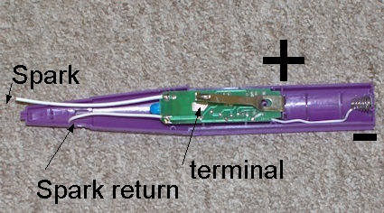
| To open
up this particular igniter there is a single
screw access from the rear of the case using
a very small cross head screw driver.
When
open this is what you see. It is very
important to keep a check on which wire
goes where else failure is inevitable as
electronic circuits do not work when
powered back to front ie - and + reversed.
The
push switch is held up by a piece of
spring steel that may well be used in the
project in another section.
When
the spring is pressed it joins the +
terminal of the battery to a little pad
marked "terminal".
It is
important to note which is the spark
return and which is the spark. The spark
return is common with the - terminal and
would be attached to the chassis of the
motor.
That
going to the spark will be the HT going to
the spark plug.
|
 |
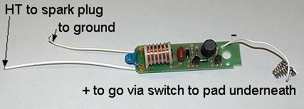
| This is
the PCB from inside the igniter - removed by
releasing a small screw adjacent to the
spring clip.. The various wires have been
identified but note they refer only to this
igniter others may be different.
It is
very important to know which is the HT and
which is the GROUND mixing these up will
almost certainly ruin the igniter or
worse.
The
next stage will be to set up the igniter
with a spark plug and prove or otherwise
that a spark can be generated.
|
 |
| 14th
October 2010
The
whole unit was taken to an friend who is
up on electronics and he is to run some
tests to see what is the potential to use
the unit to create the spark.
17th
October 2010
His
tests have resulted in a spark across the
spark plug so it does look like this idea
might well work!!
|
|
| 20th
October 2010
Further
tests have shown that the automatic
repeating spark can be stopped and the
spark created on demand by removal of two
components.
Due
to the complexity of the electronics and
the very high voltages generated ( likely
to be in excess of 10,000V ) further
experimentation must be left to those who
under stand what they are doing.
Suffice
to say that the use of this item does look
exceedingly promising.
|
 |
| 26th
October 2010
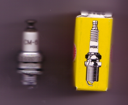
The
spark plug used is a :-
- Traditional
Spark Plug NGK Spark Plug CM-6 5812
- Gap
0.016" (0.4mm)
- Thread
Size M10x1mm
- Reach
8.6mm (.339")
- Hex
Size 9/16" (14.3mm)
- Gasket
Seat
- Non-Resistor
- Solid
Terminal Nut
- Heat
Range 6
|
Better
picture soon !!
|
16th
October 2017
I have returned to the web diary of my build
as I have changed the ignition system.
A friend of mine who has worked on cars and
earlier on motor cycles offered to sort out
the ignition system and help me to
understand what is required.
The drawing may look like it is on the back
of a "fag" packet but it is actually on the
box in which the coil and capacitor were
delivered to me.
Note that the positive connection of the
battery goes to the chassis as it would have
done on the motor cycle.
The following was suggested :-
12V Ignition Coil With Bracket Ideal for
Classic BSA-Triumph-Norton-Motorcycle and a
Lucas-Condenser-As-fitted-to-BSA-C11G-1954-5.
These were purchased from Ebay. |
 |
What
can only be called a "lash up" was done to
prove that it is a viable solution.
It is viable and a great spark is obtained
even with a very short charging of the coil
as the current arrangement allows.
The "points" have a small run where the
contact touched before the breaking of the
contact takes place causing the spark.
|

|
Having
cranked the flywheel over many many times
and sort of had a few firing a better way to
turn over the engine was needed. Whilst I
have no picture of that it was found that be
depressing the inlet valve the flywheels
would turn over and there was no
compression.
An other lash up of an electric drill and a
buffing head was put to goo use. By applying
the buffing head to the flywheel and using
the electric drill and with the inlet valve
depressed the speed of the flywheel far
exceeded that of the crank and soon the
engine was spluttering to life and
adjustment could be made to mixture and
amount of air with the druill still cranking
the engine.
It was found that the mixture needed to be
set at one half a turn from fully closed and
after the fuel had been sucked up the tube
the choke cracked open. |

|
The
engine ran until the fuel ran out, as we
were only using a small pot of fuel but the
water did boil in the cooling head.
It has been decided that the engine would
benefit from being able to adjust the timing
point whilst it is running in addition to
the fuel mixture and air ratios.
Work on the engine is therefore ongoing ...
|

|


 TO
BE CONTINUED
TO
BE CONTINUED