| 13th October 2010
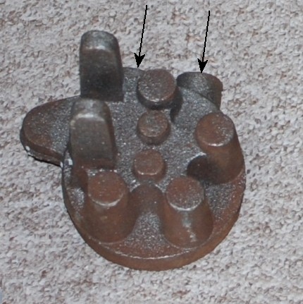
You can see from the picture that this
is going to be a very difficult item to machine.
1. because it is cast iron
2. because it is a very awkward
shape.
It has been suggested to me that I should
start with drilling the 5 fixing holes that will hold down the head onto
the cylinder liner.
With those drilled it will be possible
to make up spacers that can fit onto bolts that will pass through the holes
and then mount onto a face plate or round or square bar and hold in a three
or four jaw chuck.
Of course this
is not practical as the bolts will come through the face that I wish to machine
!!!
It is suggested ( on the
Model Engineer
forum and search for Economy engine ) that :-
Mounting the cylinder head on a piece
of aluminium angle, for use in the 4 jaw chuck on the lathe. This will allow
machining of the spigot that fits in the cylinder and the under surface of
the head. Once this is done, the head can then be mounted in the vertical
mill, with the DRO zero'd at the centre. Then all the flat surfaces can be
machined and the holes drilled.
Now that sounded a great idea but in
the end was not used!! |
 |
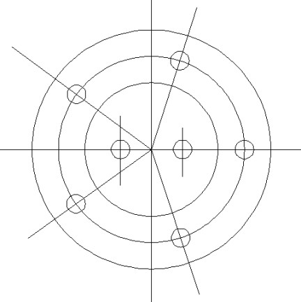
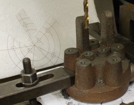
| In Autocad I drew up a circle of
holes on a 60mm PCD and then printed it out 1:1 onto a sheet of clear acetate.
I can then make various cut to that it will fit round the obstructions and
then check the location of the castings bolt positions.
The drawing opposite is NOT TO SCALE
as I have found that only a drafting program can give you the accuracy to
put the holes in the right places, but it what I drew up to use.
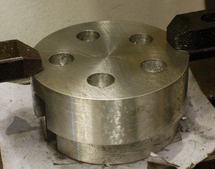
The casting has location points of the
5 stud holes and they are 17mm diameters upstands. The outer circle represents
what is the most out part of the upstand and the inner circle the inner most
part.
This then facilitates placing the acetate
as accuracy as possible on the casting and marking where the holes are to
be drilled.
Next a check will need to be made as
to how flat the casting is as it will need to be held down do that the top
to the drilling holes can be machined flat.
|
 |
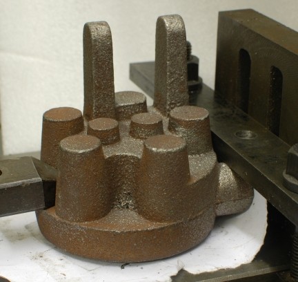
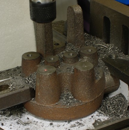
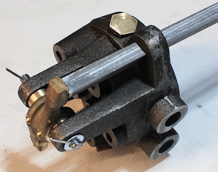
| 25th October 2010
After nearly two weeks of deliberation
I have decided how to tackle the preparation work for the machining of the
cylinder head by this method and not as described above.
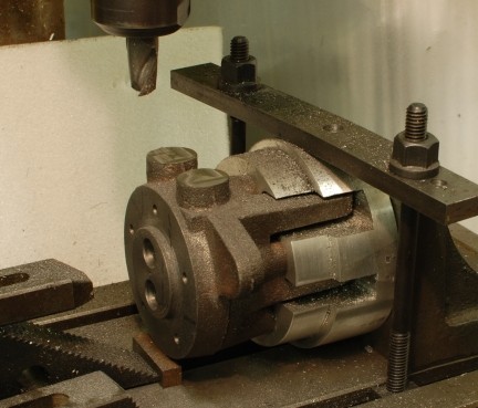
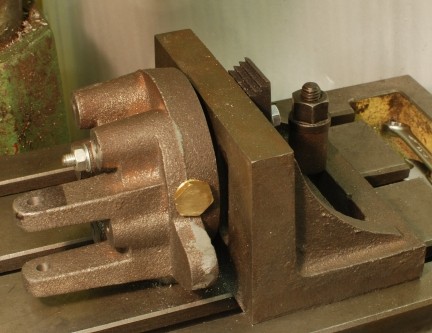
The photo shows how the head was securely
held on the milling machine.
I had previously checked that the base
was flat to within reasonable tolerance. |
 |
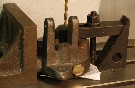
| Very light cuts were then taken with
my longest cutter as it had to reach down to the face to the bolt fixing
between the two lugs.
Due to careful leveling at the setting
up stage only 0.5mm had to be machined off.
This now has achieved a datum from which
all other measurements and any adjustments can be made. |
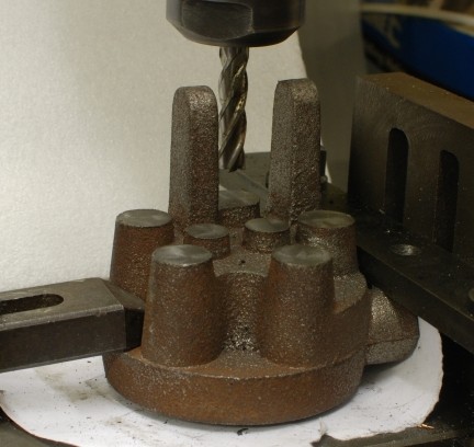 |
| The laser spot was used to align
the holes which had been centre popped through the acetate mentioned
above.
All the holes were drill 5mm so that
the outer 5 can be tapped M6 an thus act as temporary bolt holes and then
in due course clearance drilling can be carried out. |
 |
| The two vale guide were drilled out
to 5.5mm so that they can be reamed 6mm. |
 |
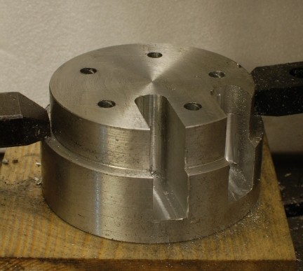
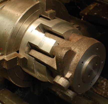
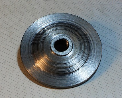
| So that the head can be held in a
4 jaw chuck a substantial base was machined from aluminium with holes drilled
to take the fixing bolts and slots machined to take the lugs. |
 |
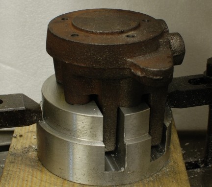
| So this is how the head will sit
on the base for machining in the lathe. |
 |
| The reverse side of the base was
counted bored with a slot drill to a depth of 10mm so that the head of any
bolt / studding will not be proud of the surface. |
 |
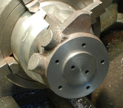
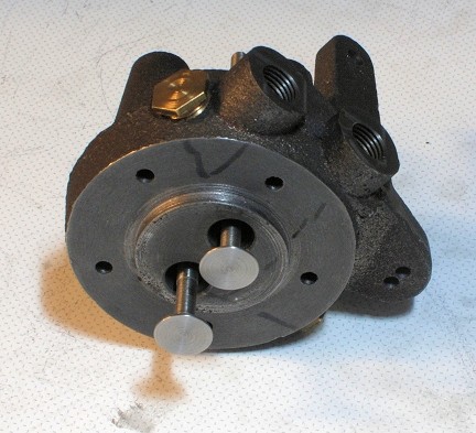
| Here the head has been attached to
the base with 5 M6 studding and nuts and washers.
It set quite easily into the 4 jaw chuck
and the centre pip which had been applied using the acetate above but of
course the other way up was aligned with the laser pointer. |
 |
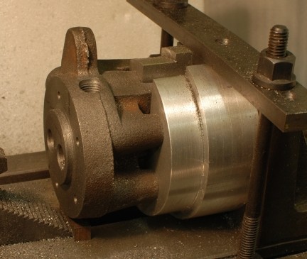
| The actual machining took but a fraction
of the time to make the base.
Note:
Had I thought
ahead more clearly such as I have done whilst chatting away to a friend I
would not have drilled the two valve guide hole from the top but marked them
to be drilled from the inside as I did to put the centre pop in the correct
place where the acetate was used the other way up to keep it consistent with
the orientation when on top.
That would
have relieved me of having to do very careful lining up to drill through
correctly and I will not know that I have done so until I have the valves
made and lapped in and proved concentricity. |
 |
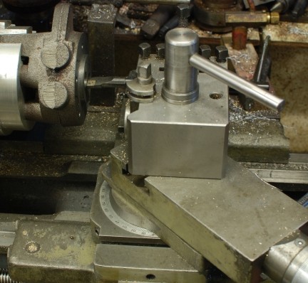
| 26th October 2010
The next take is to drill the valve port
and make the 45 degree angle on the face.
The unit was aligned using a DTI and
then drill 22mm deep x 12.5mm.
The chamfer was put on using a boring
bar with cross slide set over to 45 degrees.
|
 |
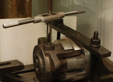
| 27th October 2010
The new 6mm reamer arrived so I was able
to ream the first hole and the set up for the second hole as was done for
the first hole.
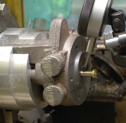
This picture shows the boring bar set
up to do the 45 deg angle. The top side is set over to 45 degrees and the
tool then cut at the 45 degree angle as required !!
Very fine cuts were made to provide the
seating prior to grinding in later. |
 |
| 29th October 2010
The cylinder head is set onto the milling
machine and light cuts taken across the top to the port exits.
|
 |
| The first holes was then drill with
1/4" drill to the intersection of the post and side cross way ( which still
has to be drilled and tapped.
Then a 8.75mm drill was used to enlarge
the hole and finally a tapping drill for the 1/4 BSP.
Then the hole was tapped. Note the point
held in the chuck this was to ensure that the hole was made
vertical. |
 |
| Similarly with the second hole
!!!! |
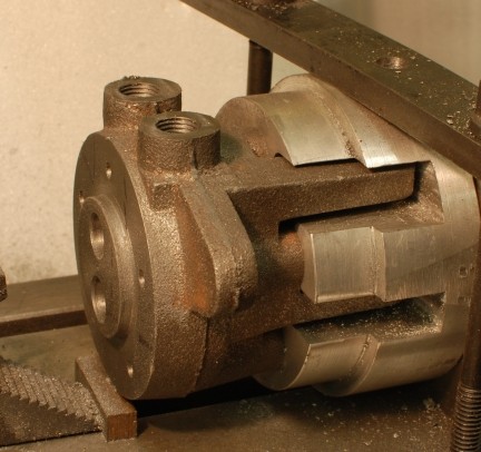 |
| The additional cross way passage
to link port to outlet completed. |
 |
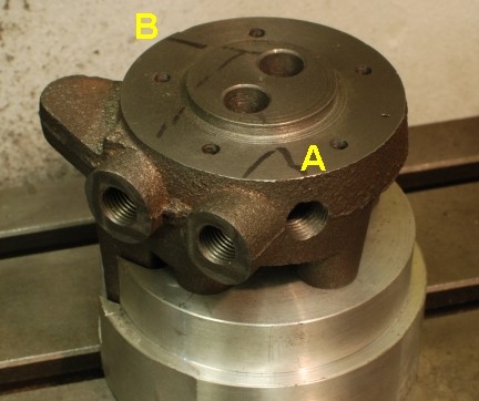
| Here is the other one. You can see
the "general idea" lines marked on the casting to ensure no major mistake
was made!
There is not too much left to do on the
cylinder head:-
Drill and ream for the valve rocker and
Drill and file out square the support
for the valve linkage
Make up the blanks for the holes to seal
off the passage ways that will be used at points A & B which should have
been 1/8" BSP and I have made them 1/4" BSP still what is the difference
in size between friends !!!! |
 |
| 30th October 2010
The cylinder head is set up to drill
the holes to take the rocker arm.
It is bolted firmly to the angle plate
with the inlet and outlet set on the mill bed.
After drilling the hole was reamed
6mm. |
 |
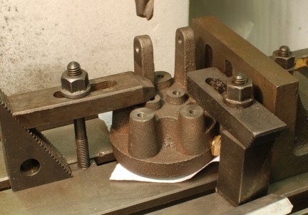
| The cylinder head is set up to mill
the 25mm gap in the rocker supports. |
 |
| The cylinder head is set up to drill
two holes which will be filed out to size to the rocker push rod. |
 |
| The head and its valves. The valves
were turned from Stainless steel and still need to be cut to length, cross
drilled at their top end to secure the return spring and then finally ground
into position.
|
 |
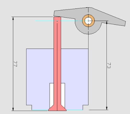
| The dimensions on the drawings did
not quite work out to the casting so the hole holding the rocker arm was
moved by 6mm to 79mm above the base edge against the 73 as shown in the
sketch.
The original size of the valve is also
shown as 77mm over all but it will need to be made 83mm over all to correspond
with the raised rocker centre.
The push of the cam is 4mm so that
will bring the rocker for all allowances to the horizontal which is
as shown in the general arrangement drawing. |
 |
| 1st November
2010
A friend who know about these things
showed me the way to grind in the valves. Rather than starting with course
paste he started with fine and in a few minutes the job was done. I operated
an battery drill whilst my friend pushed the valves into the seating. Then
the pressure was released and more paste applied.
To check all was well the paste was washed
out with WD40 and then the valve held closed and WD40 put into the exit hole
associated with the valve. No WD4 came through the valves which being a very
find liquid certainly would have found out and leaks.
The real test will come when the engine
is fired up. |
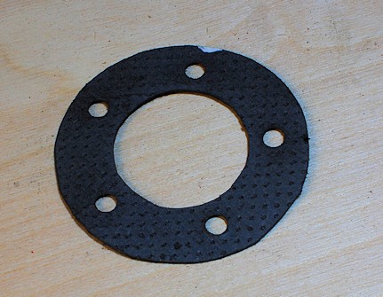
| 9th November 2010
I have made a gasket but the material
I chose was not right but I have proved the method.
More material is on order
Draw the inner circle and then the outer
circle. Cut out the blank. hold it in place on the head and push the gasket
into the securing hole and you will have a little indentation to show where
to cut the small holes.
I made up a cutter to 6.5mm by drilling
a piece of silver steel, then apply a 10deg taped, polish, harden and temper
and lastly clean up for use. it would perfectly and still has a very spar
edge as I used end grain wooden block to hit against which does least damage
to the cutter.
The white blob is to identify the bottom
of the gasket.
|
 |
| 10th November 2010
The rectangular hole for the push rod
has been made and the push ron reduced from 1/4 x 1/2" to 5 x 10mm.
So the head other than checking and finally
fixing the plugs is ready to be installed.
|
 |
| 18th November 2010
The rear fixed part of the exhaust was
machined and threaded 1/4" BSP to take the link pipe to the elbow onto the
cylinder head. |
 |
|
|
|
|


 TO BE CONTINUED