Machining
the flywheels
|
| 30th
September 2010
Without
the stock to start machining parts I decided
to take a look at the flywheels.
I
thought that as I have a BOXFORD with a 5"
centre height that all would be fine BUT
when I went to turn the flywheel I found
that the castings were about 10.7" and thus
I could not fit them into the chuck.
As my
lathe is very old, bought in about 1983 I
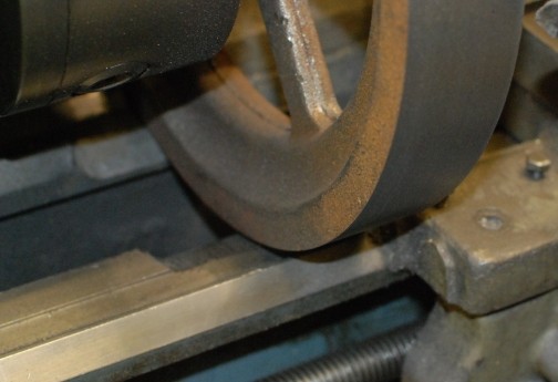
decided to do a small modification. So out
with the angle grinder and I cut away the
lathe bed just sufficient so that I could
machine the flywheel.
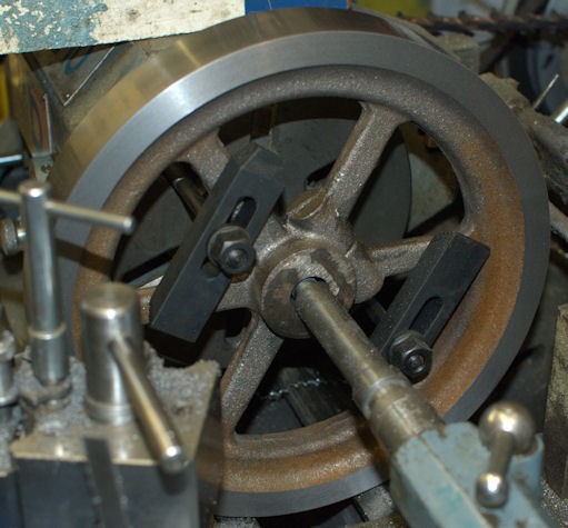
You can
see the section cut away and how small a gap
was left after the fly wheel had been
machined on the front and edge face.
|
 |
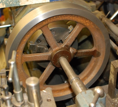
| I had
wanted to set up the flywheel in a four jar
chuck but with the difficulty of the size of
the lathe I decided to use the 3 jaw chuck. I
made the face as true in the chuck as
possible. I then used a centre drill to make a
small centre hole with the idea of using my
revolving centre to steady the flywheel whilst
being turned. I then found to my horror that
the tail stock with centre would not reach the
wheel because as I had had to cut away part of
the lathe bed but this did not allow the
saddle to pass under the flywheel (look at the
picture above).
|
 |
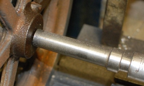
| I found
that I had previously prepared a Morse taper
blank and had also put a centre hole in the
other end. So with the aid of a 1/4" ball
bearing I was able to hold the centre firmly
whilst turning.
|
 |
| Out of
necessity the lathe tools had to have a large
over hang but with very gentle cut the front
face was machined.
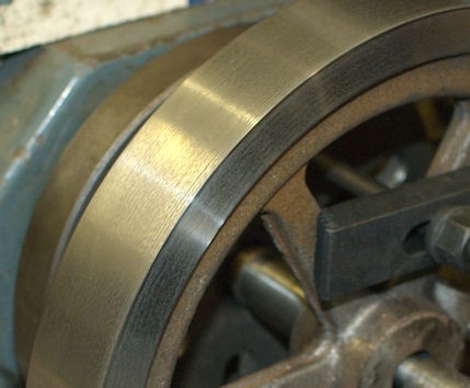
Then
how was I to machine the outer edge. I
decided to use a substantial boring bar
mounted up side down and revolved the lathe
in the opposite direction to normal.
Due to
the significant over hang of the tool it
experienced quite a lot of chatter so I
clamped a shallow V block to the side and
this made a great improvement.
|
 |
| With that
completed the next task is to bore the hole
and as each flywheel has a different size hole
one is 20mm the other 17mm this need care.
First I
drilled through with a 3/16" drill and then
with a 1/2" drill and then bored out the
hole to 20mm.
This
drilling and boring process took about an
hour to do.
|
|
| 1st October
2010
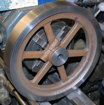
To be
able to machine the rear of the flywheel I
replaced the chuck with a face plate and
inserted an arbor into the head stock. The
arbor was machined to give the flywheel
something to "sit on" and prevent sideways
movement during the machining process.
The
flywheel was then attached to the face place
with two large bolts and cross pieces and
then clocked with a DTI (Dial Test
Indicator) to run as true as possible
(-/+0.003" was achieved).
When it
was being machined the cut was 0.3mm and the
cross slide moved under "hand power" but for
the final two cuts of 0.1mm and 0.05mm under
power from the lathe.
|
 |
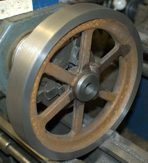
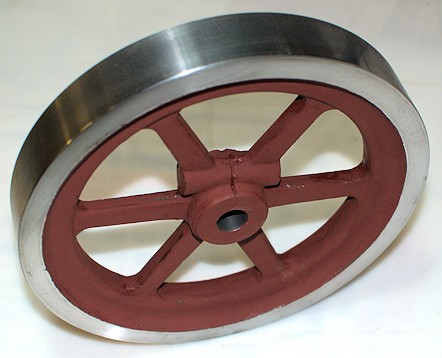
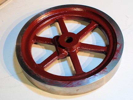
| The side
of the flywheel was then given a "shine" with
progressively finer wet and dry and then
lastly some oil rubbed into the "shine" in an
effort to prevent rust !!!
The
flywheel will be painted where it has not
been polished !
The
second flywheel will be similarly machined.
|
|
| 2nd
October 2010
Machining
started on the second flywheel this morning
but this time it was initially held in a 4
jaw chuck as I had centre popped the boss
after taking measurement from the edge as
the boss off centre and would not fit the
three jaw chuck. Front edge first, then the
outside and then the hole drilled and then
bored for the 17mm shaft.
|
|
| Both
flywheels had a round file applied to them to
removed the excess "flashing" and suitably
prepared for the application of a metal
primer.
So the
flywheels are now completed except for
cutting the key way in each.
|
|
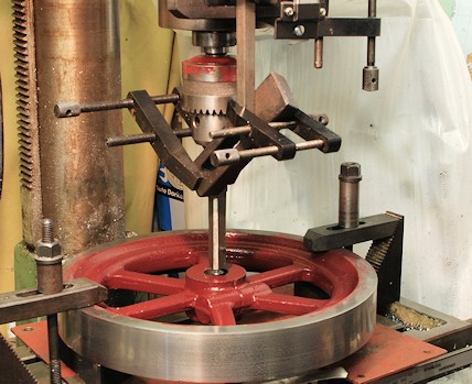
| 11th
October 2010
Both
Flywheel received a second coat of paint.
Maroon colour by Craftmaster.
|
|
| 13th
November 2010
The
tool to cut the key was was made up and the
one of the fly wheel set on the mill to cut
the 2mm deep keyway.
The
arrangement of clamps was to stop the shaft
rotating whilst the keyway was being cut.
|
|
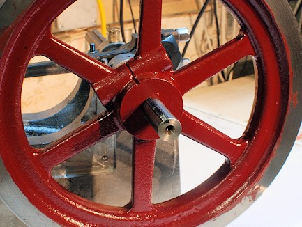
| Here the
flywheel is set on the crank with key. Final
fitting has yet to be sorted out. |
|
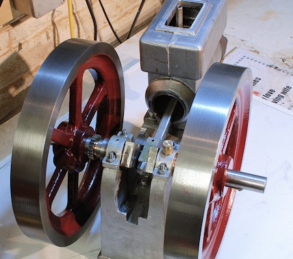
| Second
flywheel key-way machined and now second
flywheel fitted. |
|
|
|