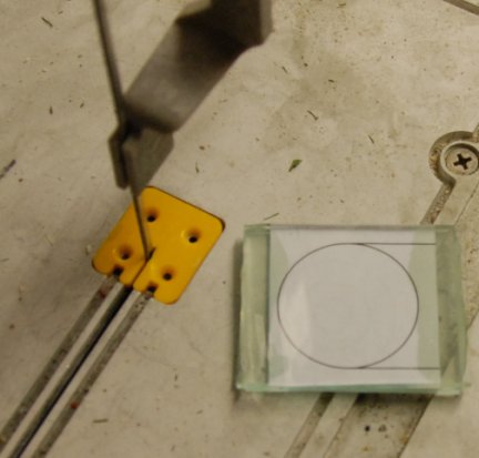
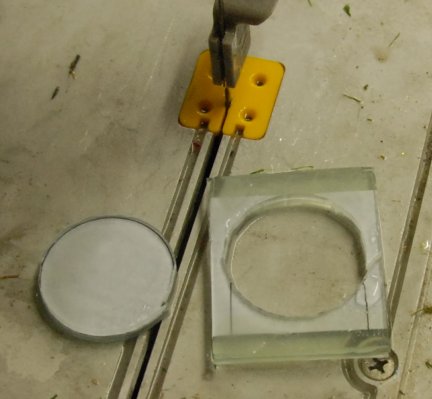
To do this I draw in the CAD package
the circle and printed it out 1:1 onto paper. |
 |
 |
 |
 |
| I sandwiched the paper between two
over size pieces of glass having first applied to the left and right edge
Araldite Rapid.
The idea of using fast setting Alradite
was given to me by my close friend John Mallichan.
|
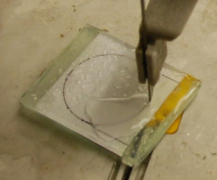
Having previously made
Stained glass windows I own a glass cutting saw so I was able to cut out
the two circles of glass at 34.5mm as accurately as possible |
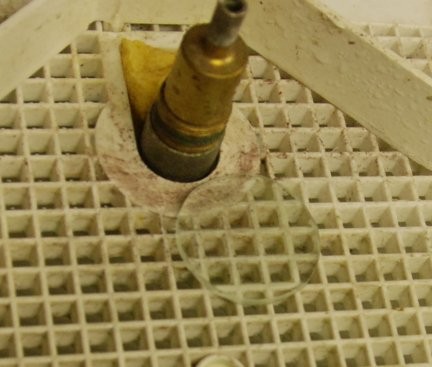
Then with the diamond dressed grinding
wheel ,also from Stained glass days, I ground away the slight excess. To bring
to size I placed a fence 34.5mm away from the cutter and then used this to
bring to final size. |
|
| 20th July
2009
Visited
Western Steam
Model Engineers Burnham-on-Sea. TA8 1EY who I have commissioned to make
the boiler. It should be ready the end of November beginning of December
2009. |
| 23rd July
2009
Made the main axle a good fit to the
main driving wheels. Decided to purchase a 300mm digital calliper to make
accurate measurements more readily. |
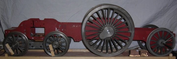
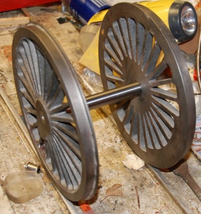
This is my Stirling Single as current
with the main driving wheel with their axle and the training wheels needing
the axle to be made.
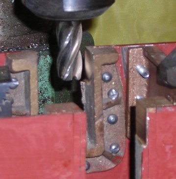
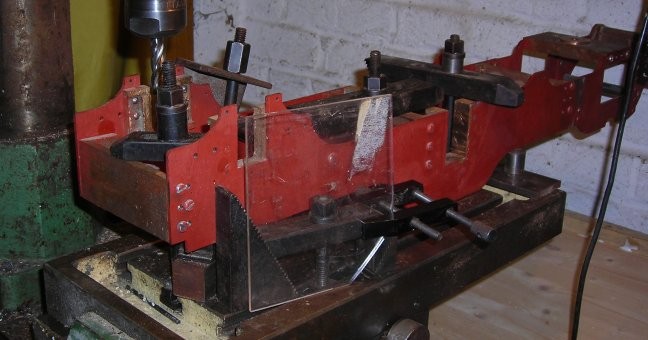
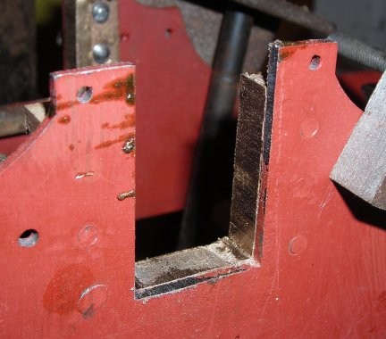
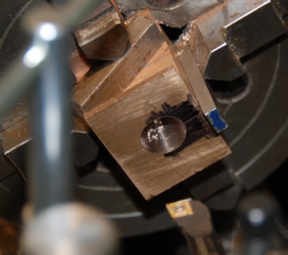
This evening I set about the task of
setting up the milling machine ready to cut the main wheel horn blocks. This
may not be the usual way but it was the way I did my Sweet Pea loco 20 years
ago and that is still running. The setting up took 2 hours!
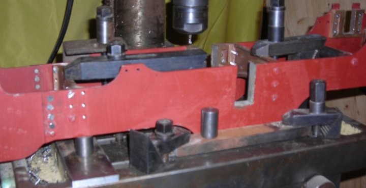
The round piece in the centre of the
picture is the gauge for the width of the horn blocks. |
| 24th July
2009
In the morning work started on the slow
and careful mill cutting of the main axle horns. |
 |
|
Taking a limited depth of cut |
|
 |
|
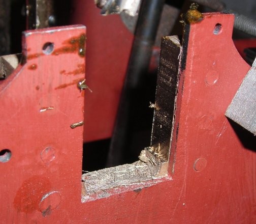
The cut has now been taken as low as
possible and the remainder has to be filed out! |
|
|
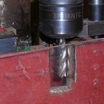
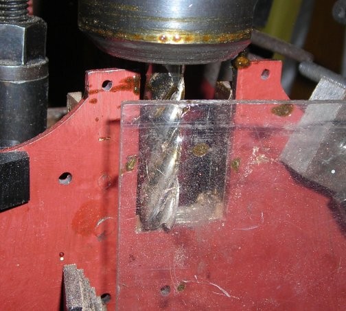
Having taken the cut as deep as the other
cutting tool would go I changed to a thinner but longer tool. Note the plastic
sheet as some protection from flying fine cut particles.
After quite some time the trial block
fits nicely and the job is done. |
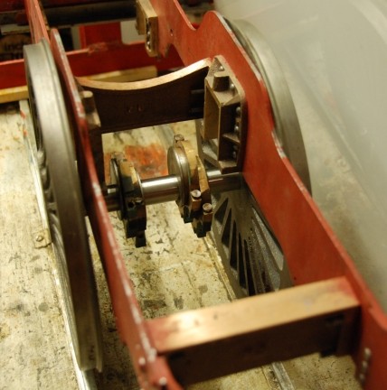
In the evening of the same day
!!!
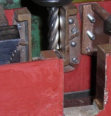
The set up for machining the last pair
of horn blocks. cutter was carefully aligned so that the frames were square
to the cut. |
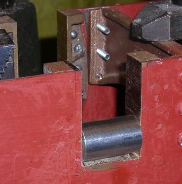
First side completed as far down as the
cutter will go |
Both side completed as far as using the
cutter |
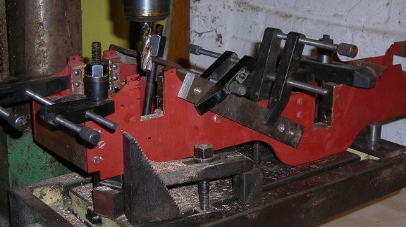
Compare this with the initial set up.
The additional clamping was to remove as far as possible vibration of the
frames. |
The completed horn blocks after filing
has been completed. |
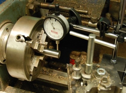
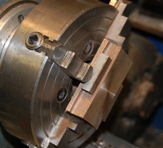
| 23rd July 2010
Made up the axle for the driving wheels.
To make sure that the axle runs true it is clock in a 4 jaw chuck until the
error is only very slight and of the order of 1/1000th of an inch.
The shoulder is then machined to size
and centre drilled. |
 |
| Once one end was completed the length
of the bar was cut about 4mm over size pit in a 3 jaw chuck to face off and
then carefully measured.
With the measurement known the bar is
then set up again in the 4 jaw chuck, clocked for true centre machined back
to overall length, shouldered and centre drilled.
With that done the axle was tried in
the wheels and the fit was very nice and sat on the rail correctly. |
 |
| Here the frames have been moved to
building jig and the cylinder put in place as well as the
wheels. |
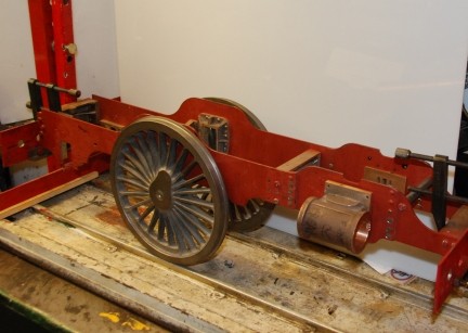 |
| The main axle will hold the two sets
of eccentrics for the valve gear and the single eccentric for the axle
pump.
The eccentric are complete except for
the absence of the axle pump eccentric. |
 |
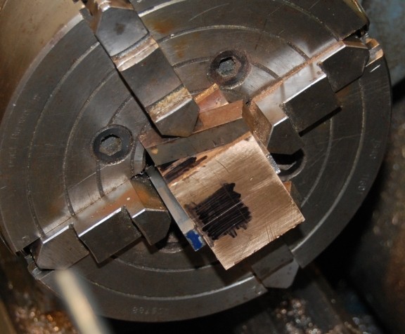
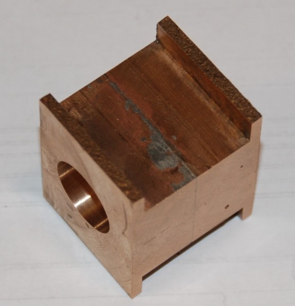
| 26th July 2010
Today the axle blocks were brought to
thickness (as shown in the picture) and then as with the other axle blocks
were machine to size of width to fit the axle horns and the correct amount
of step depth to the outside.
The block was then sawn in half and solder
flux applied and a small amount of solder and the two halves brought together,
aligned on the sides and then press down so that there is a zero gap for
the solder. A check round to find all was ok - this was done by
measurement.
The part now as one were placed in the
4 jaw chuck and aligned square and the top faced off followed by the
bottom.
Marking out then took place and the face
to be aligned with the laser pointer.
The drilling and boring will wait until
tomorrow or later when a check of the alignment will be made.. |
 |
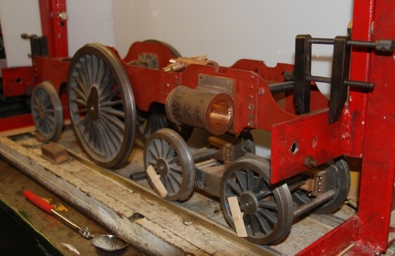
| This is how much has been done of
the loco .... |
 |
| 26th July 2010
The picture show the axle box set up
ready to drill and bore. |
 |
| The first small drill has gone through
followed by a 1/2" drill and now ready for the boring bar to bring out to
size.. |
 |
| The completed pair of axle boxes.
You can see the solder line on the sides. |
 |
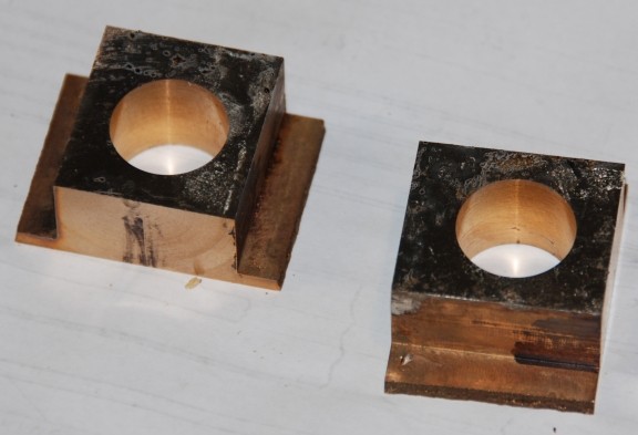
| The two boxes now separated. A great
deal of heat was required to melt the solder and the parts took a long time
to cool ready to clean up and complete the machining according to the
plans.. |
 |
| 14th August
2010
Today I machined the trailing axle boxes
on their sides to fit the training horns and also to thickness over all which
leaves cutting the block into two and then drilling for the axle. |
| 15th August
2010
The axle box was cut in half, soldered
internal face to internal face, ends squared up in the lathe and then the
hole for the 1/2" axle marked out and then drilled. The reamer became stuck
in the final pass but with gentle easing moving the chuck against the reamer
it was removed and the hole then bored out to size. The reamer is to be thrown
away as it is blunt !!!! |
|
|
|
|