The building of a Stuart S50 Engine
The cylinder needs to be compared to the drawing as it is necessary to know which end of the cylinder has to be at right angles to the bore.
The photo shows the casting against the drawing and the end from which the piston rod will emerge has been marked with marking out fluid so that no mistake can be made.
A check was made that the caste bore was very close to the exact centre of the casting by measurement of each end to the outer diameter of the casting.
It was found to be very true.
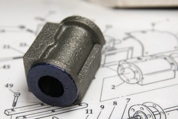
This will then be used to aid the set up of the casting in the Lathe's 4 jaw chuck ready for boring and facing of the outer end which on the right hand end in the photo.
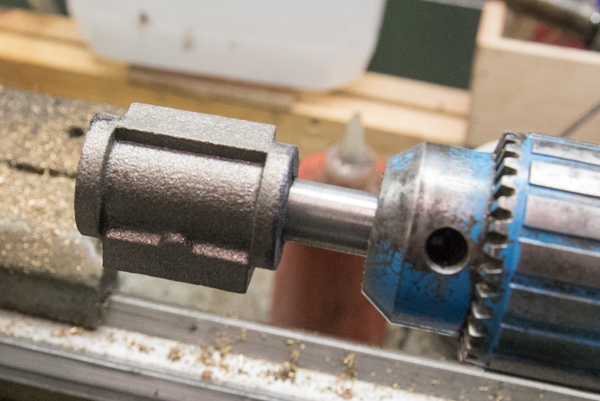
The photo shows how the mandrel in the tail stock chuck has been used to position prior to clamping down fully in the 4 jaw chuck.
the mandrel was then taken out of the casting and the jaws gently tightened down using the packing piece to stop damage to the the surface of the casting. Note the blue end is outermost so that it can be machined following the boring.
The bore will be made 5/8" which I convert to metric as my lathe has metric divisions.
I will be using a tipped tool to bore the cylinder out to the correct size.
When the boring takes place the mandrel will of course be backed away else the tool could not fit in the bore !!!
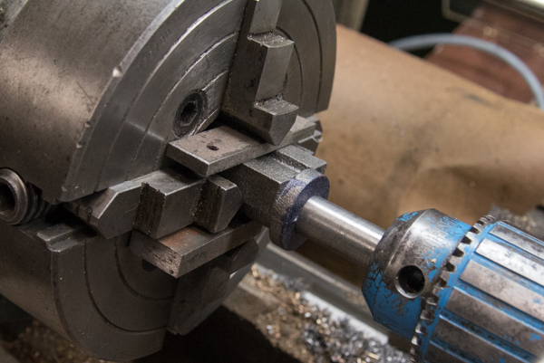
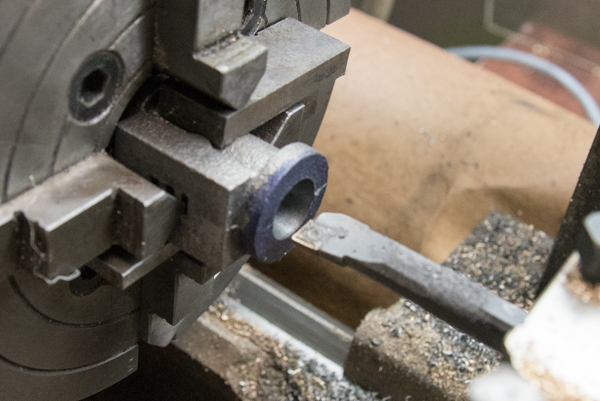
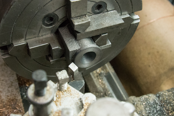
The boring bar is ready to make the first cut to the cylinder and ensuing that I cut below the finish of the casting else the tool would be blunted easily.
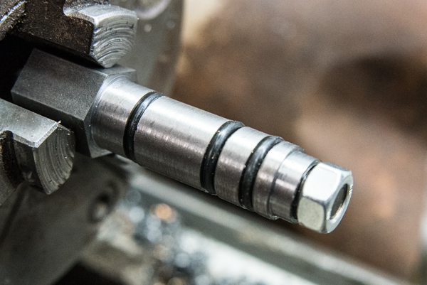
I watched another of Keith Appleton YouTube videos where he shows the use of a mandrell made for the purpose with two O rings.
I decided to make a variation on that and used 3 O rings.
The O rings are supports on a bar made a snug fit inside the O ring and the O ring chosen so that with a little persuarion it would enter the bore of the cylinder.
The nut on the end is used to compress the spacers and thus expand the O rings to hold the cylinder tightly.
If you look carefully you can see that the outer most spacer is relived slightly so that when the end is machined the lathe tool can pass right across the outer part of the face.
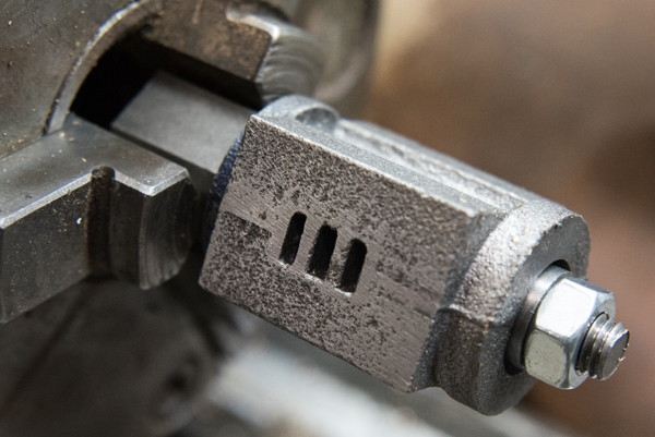
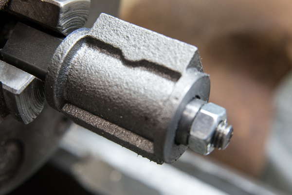
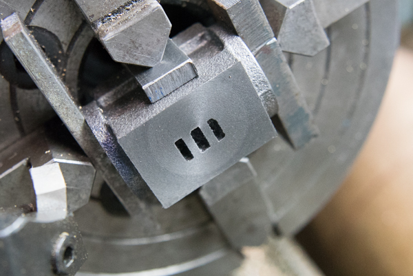
The cylinder needed to be set up in the 4 jaw chuck to face the ports at right angles to the bolting down side.
I assess ed that the bolting down to the base was reasonable accurate but there was a slight angle from right angle to the port face. With this in mind packing pieces were used to protect the faces for the end caps and a spacer used to ensure the bolting down side was at right angles to the chuck.
It was all gently tightened up and a check made as to squareness across the face relative to the bore. It all looked good so the machining took place and the result can be seen in the photo prior to release from the chuck and final polishing of the port face on fine wet and dry.
All in all a good hours work.
Much thought has been given as to how to drill the cross ways accurately and I also referenced back to my web site on my Stirling Single build.
Previously friend sent me this instruction and the drawing.
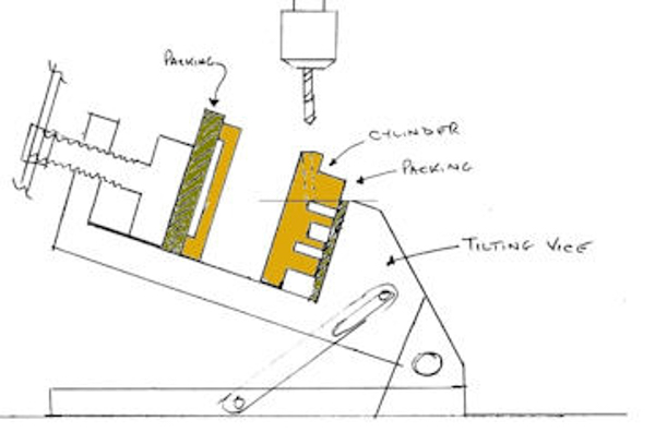
"I have always used the tilting vice that came with my mill. The cylinder is set in the vice with soft packing against the jaws and careful not to crush the bore. The vice can then be angled to the correct angle when sighted against a drill in the chuck with the side of the casting as you know roughly where the ports are and how deep they are. If you set the jaw packing level with the top edge of the top port, it is easy to see where the drill will break through. Use an end mill first to create a flat on the end of the bore big enough to cover the area of the passages. Then use a small centre drill followed by a drill to complete the passages. Then turn the cylinder up the other way and do the other passages the same way. Simple!!"
The drawing show a cross
section through the casting of my Stirling Single but the
principles are the same. I did not read the above very closely
as in the drawing you can see that the post is not aligned with
the top of the packing.
It all sounds so easy but of course it is a job not to be rushed under any circumstances else all the previous good work of boring and facing will be for nothing.
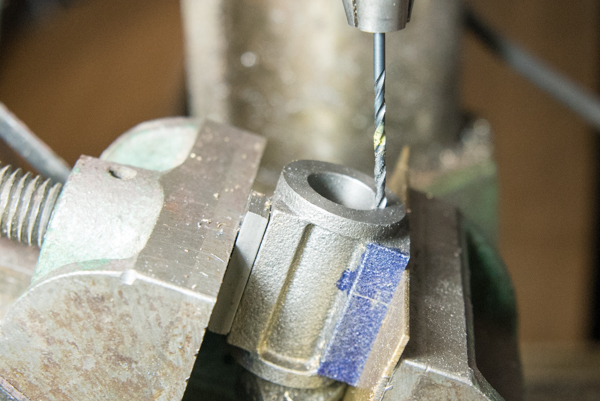
I set the cylinder is set in
the vice with soft packing against the jaws and being careful
not to crush the bore.
I then angled the vice by sighting the side of the casting against a drill in the chuck and double checked the location several times.
Then I used a small slot
drill and made a flat upon which I could land a small centre
drill just slightly bigger than the 3/32" drill, bought new to
do the job, to make the port. Using the slightly larger centre
drill ensured that the drill went into a hole and did not slide
down the bore.
With the positioned checked
to allow for two drilling and the drill marked with Yellow nail
varnish to show the depth the drilling commenced.
Very gently pressure was use and regular clearance of the drilling to ensure the drill did not lock up.
At the very point of break through indicated by the nail varnish the pressure released as no cutting was taking place and the first hole was drilled in to the post.
The caste iron dust was blown out of the holes and the cylinder is ready for the next stage drilling the exhaust port.
The job was completed in about 1 hour 45 minutes.
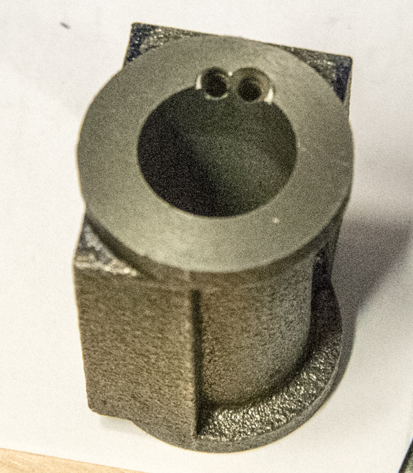
Now comes the time to drill the Exhaust Port exit and thread it.
The alignment was carried out as shown in the photo using the 3/32" drill as it is almost the same size as the port and thus easy to align.
I had already marked the distance from the face to be drilled and then used a centre drill to spot mark the location for the 1/8" drill to drill down just into the port.
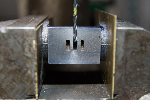
The max depth was marked on the drill and carefully drilling done.
I then tapped the hole using a suitable guide button previously made to keep the tap upright and carefully tapped the hole.
Now I need to make the end caps making sure that I drill the end cap the right size to ream for the size of the piston rod!
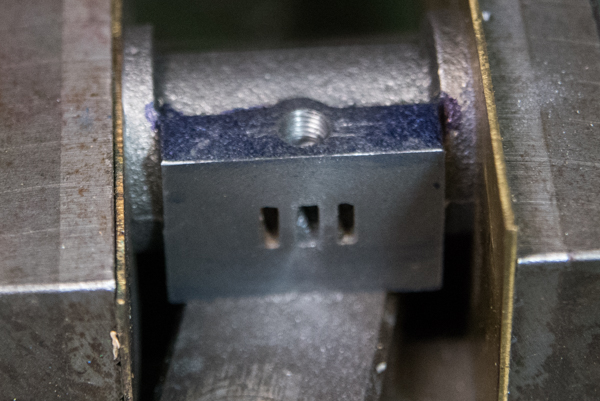
The end caps started out as a piece of caste iron bar about 2" long and 1 1/4" round.
Much very careful machining brought us to the stage shown in the picture.
First the end of the bar have to be machined flat and then the outside diameter brought to size.
Then the exit end cap was machined and drilled and taped to take a 1/4" x 32 thread.
Then the bar had to be parted off but my parting tool which is self ground could not reach to complete the job so the remainder had to be saw.
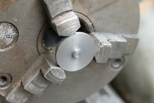
The saw off part was then carefully held in the three jaw chuck and centre drill and then drilled through one drill size small that 1/8".
The hole was then reamed 1/8".
Now the end cap was reduced to overall thickness taking very gentle cuts to reduce the possibility that the part would be thrown out of the chuck.
Finally, for that side the location spigot was machined so that it is a good fit of registration to the bore of the cylinder.
Then the part was turned round and a decorative embellishment added according to the plans which necessitated the grinding up of a tiny boring type bar to form the recess.
The photo show the end cap of the outer end which does not have the piston rod hole !
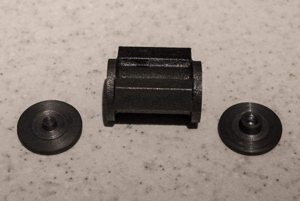
The photo show the two end caps and what will be the visible ends when completed on the working engine.
No photo today !!!
Today I made the screw in end of the cylinder behind which graphic yarn or PTFE tape will seal in the steam.
Then I turned up the piston and mounted it onto the 1/8" piston rod.
The end caps need to be marked out ready to drill and be fitted to the ends of the cylinder.
6 holes are required so these need to be set at 60 degrees from each other.
First I marked out the PC line of 7/8" (22.2mm) with a crude pointed held in the tool holder of the cross slide.
Then in turn this was aligned with the three jaws of the chuck and marks made each side of the centre.
This results in the necessary 6 marks.
Next I will need to centre punch the marks prior to drilling.
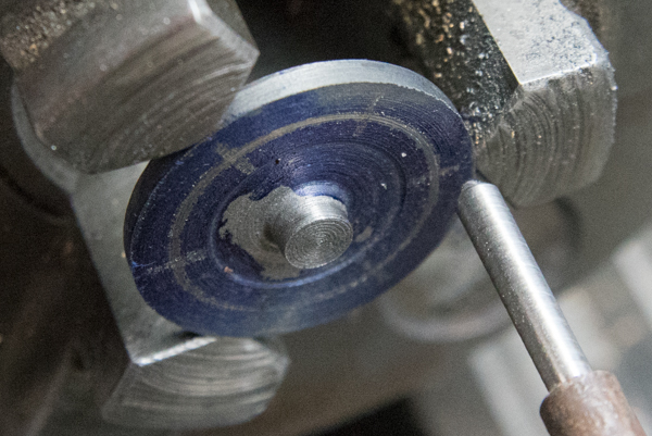
I decided to make up a holder so that the end caps could be easily drilled having been first centre punched.
The end caps were drill as seen in the photo.
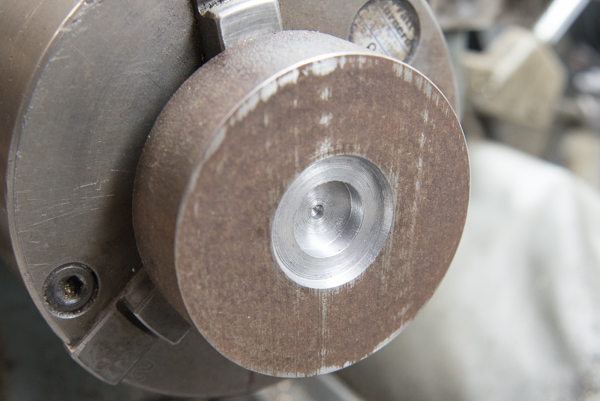
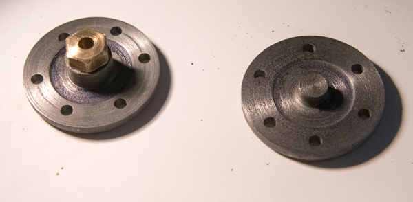
They were then temporally fixed to the cylinder with 603 adhesive as recommended by Keith Appleton.
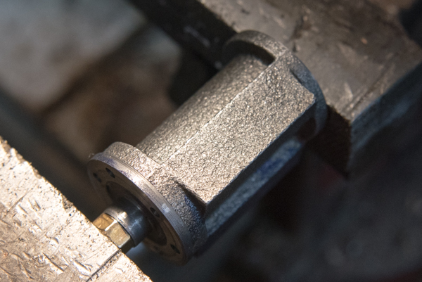
Before drilling the tapping holes I decided to make up a tap guide for the 7BA taps which could be easily held against the ends of the cylinder and as such the guide was made offset.
22nd September 2019
I drilled the holes for the tapping of each end but finding the 7BA bolt a little slack in the thread decided to amend and make them 6BA each end.
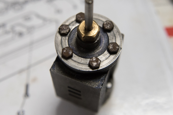
So time to make the gaskets. I had some material left over from a previous project so decided to use that even though gasket material is supplied with the kit.
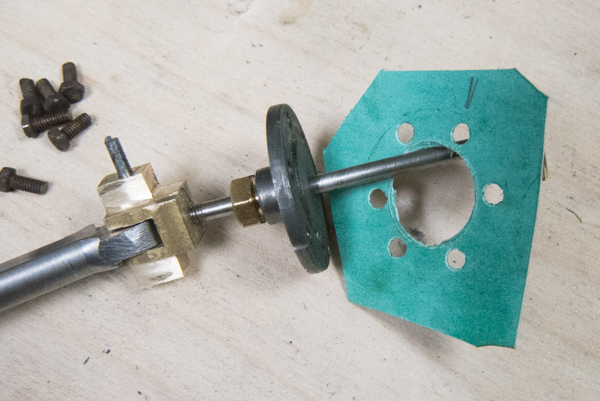
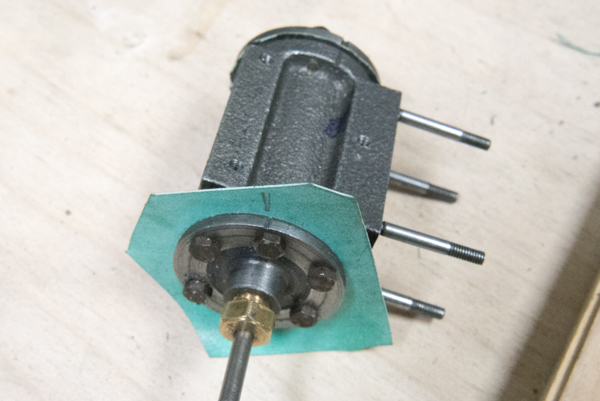
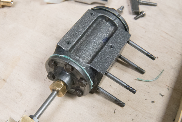
The photo shows the gasket with the centre hole cut out and the bolt holes made.
The gasket material was held against the end cap and a pencil marked the location of the necessary holes together with a reference poin which was previously filed into the end cap.
