The building of a Stuart S50 Engine
The Boxhead
Having a watched an interesting video on YouTube I decided to follow the example of Keith Appleton and use my Linisher to prepare the base of the Boxhead.
There is only a few thou to remove as the casting is of good quality.
I then placed the part on my glass surface plate which had been made by my Father in Law Don Bruce sadly now departed, and the base proved to the flat as expected and as required.
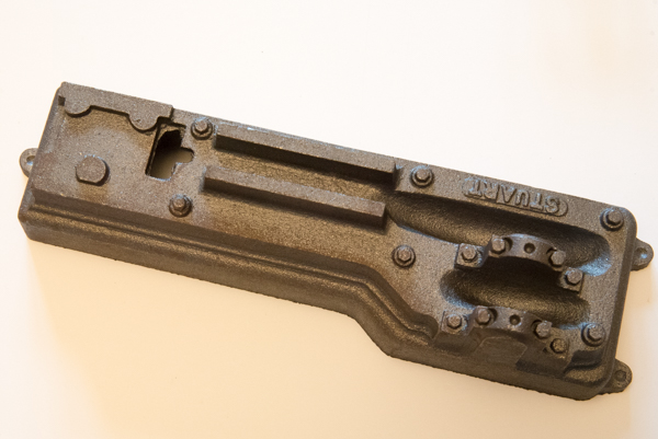
The marking out of the Boxhead did not prove to be easy so I reverted to a tried and tested way of machining up a spacer the correct length 1 1/2" and a second one with 21/64" added. I had to convert the dimensions to Metric as my lathe is Metric !
With the Boxhead proved to be without rock on the bottom I placed a sheet of paper on the mill and then clamped the Boxhead down firmly enough to hold but not too tight to risk breaking the bolt down location at each end.
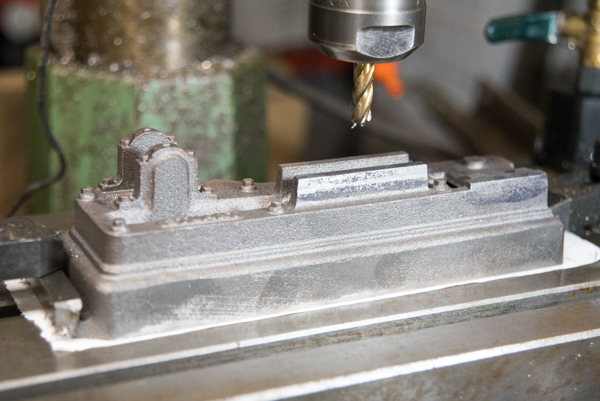
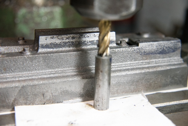
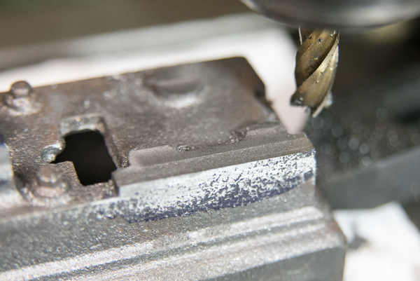
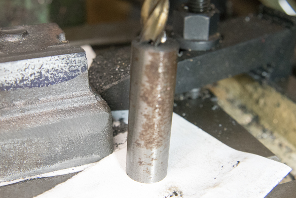
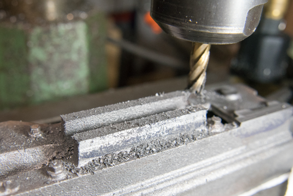
I make up drilling templates to act as guide for the holes and there by making the parts fit well.
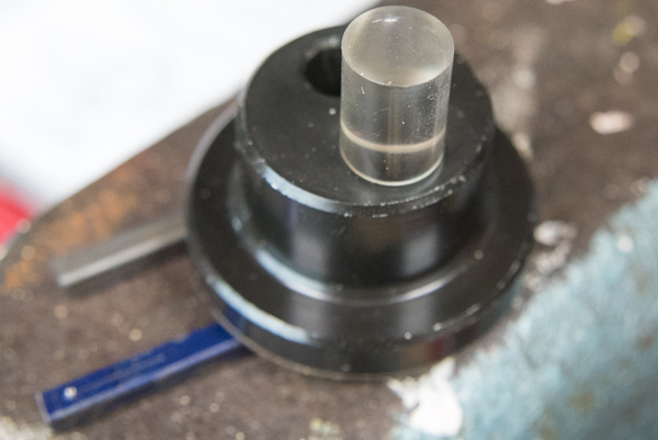
For the slide bar the templates are the slide bars themselves and the photo show an optical punch, with the optical part in the holder which is then removed when lined up and the metal punch inserted and a gentel tap to make the mark ready for drilling.
A separate piece of metal for the location for the cylinder will be used.
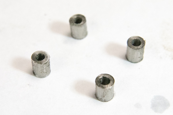
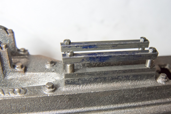
I have drilled the holes in the base in slightly the wrong place so using a Slot Drill I carefully extennded the holes towards the centre so that some adjustment is possible after locating and tapping the fixing holes in the cylinder.
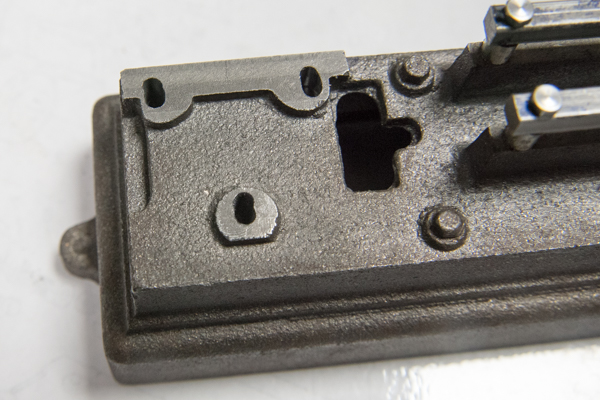
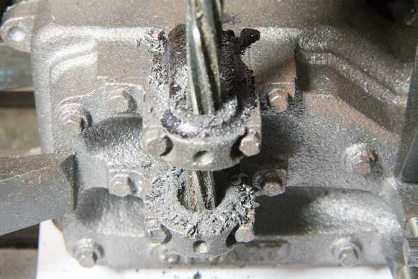
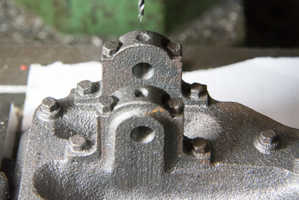
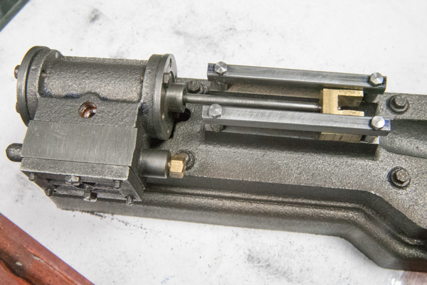
Today I was able to drill and tap the three fixing holes on the underside of the cylinder and bolted the part down and the cross head still slid in the guide bars.
You
can see in the photo that I have installed one of the bolts
holding one side down and there is also a second bolt hidden in
the photo.
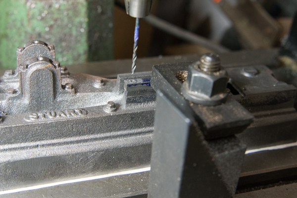
The drill is set up ready to drill the 7BA tapping hole.
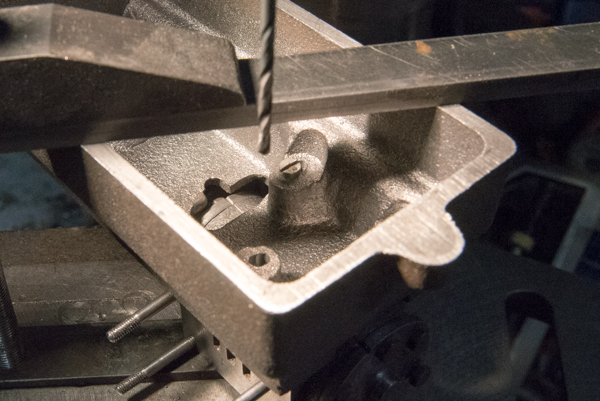
The next part to be made is the connecting rod which I have already reduced one end to 3/16" and then engineering blue applied so that it could be marked out to the dimensions as shown on the plans so the centres of the holes were 2 inches and 1316 centres
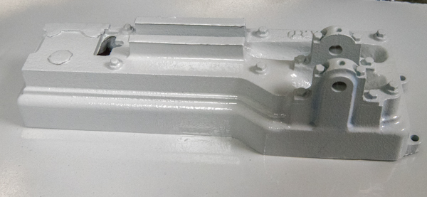
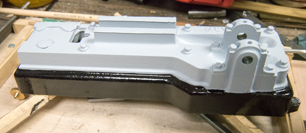
The boxhead was masked up and spray printer with a primer in readiness of the main colour being painted on.
